Cable Tracer Circuit is of two part device, which help find and check right cable in group or inside wall.
Also, it have two parts: transmitter and receiver and mostly people use it in telecom, network, fixing wires, security system and audio/video setup.
Circuit Working for Cable Tracer Transmitter Circuit:
Parts List:
| Components | Values | Quantity |
|---|---|---|
| Resistors | 2.2k 1/4 watt | 1 |
| 470Ω 1/4 watt | 1 | |
| 22k 1/4 watt | 3 | |
| Capacitors | Ceramic 10nF | 1 |
| Ceramic 22nF | 1 | |
| Electrolytic 1µF 25V | 1 | |
| Semiconductors | Transistor BC547 | 2 |
| Transistor BC557 | 1 | |
| LED white flashing 5mm, 20mA | 1 | |
| Push Button | 1 | |
| Battery 6V | 1 |
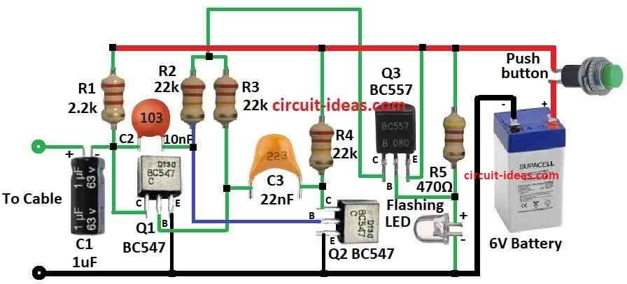
In the above circuit diagram the circuit makes LED blink and this blinking signal goes to transmitter and we can follow cable by using receiver to catch this signal.
Here is how it works:
When 6V power is ON circuit starts.
When we press the push button, current flows through Q1 and Q2 and in this circuit, the BC547 transistors Q1 and Q2 operate in a common-emitter configuration, and they amplify the signal.
Then capacitor C1 controls how fast LED blinks and Q3 transistor is common collector type and it takes signal and gives current to LED.
Next, Q3 supplies current to turn ON the LED and then, connect the cable we want to trace to the input point.
Finally, when this cable is near transmitter then receiver picks signal and makes sound.
Formula:
An astable multivibrator is an oscillator circuit that continuously switches between two unstable states on its own and therefore, it does not require any external trigger to keep oscillating.
In cable tracer astable multivibrator gives continuous signal to send through the cable.
Important points and formula:
Frequency (f) of oscillation:
f = 1.44 / (R1 + 2 × R2) × C
- R1 and R2 resistors connected to capacitor.
- C is capacitor value like C2 in the above circuit diagram.
Note:
This formula gives rough estimated frequency and for more correct result use real charge/discharge time of capacitor.
Also, to design good cable tracer pick resistor and capacitor values that give right frequency, which will help signal go well through cable depending on our need.
How to Build Cable Tracer Transmitter Circuit:
To build a Cable Tracer Transmitter Circuit follow the below mentioned steps for connection:
- First, Q1 collector goes to +6V through resistor R1, Q1 base connect to resistor R3 and then Q1 emitter goes to ground.
- Then capacitor C1 connect to cable input.
- After that, Q2 collector goes to +6V through resistor R4, Q2 base connect to resistor R2 and capacitor C2 and then Q2 emitter goes to ground.
- Also, capacitor C3 connect between R3 and R4.
- Now Q3 collector connect at point between R2 and R3, Q3 base connect from +6V to ground with resistor R5 and flashing LED in series and then Q3 emitter connect to +6V.
- Lastly, push button connect to +6V of battery.
Circuit Working for Cable Tracer Receiver Circuit:
Parts List:
| Components | Values | Quantity |
|---|---|---|
| Resistors (All resistors are 1/4 watt unless specified) | 3.3k | 1 |
| 33k | 1 | |
| 22k | 1 | |
| 220k | 1 | |
| 330k | 1 | |
| 10k | 2 | |
| 2.2M | 2 | |
| Capacitors | Ceramic 100nF | 3 |
| Electrolytic 47µF 25V | 2 | |
| Electrolytic 10µF 25V | 1 | |
| Semiconductors | Transistor BC547 | 4 |
| Transistor BC557 | 1 | |
| Coil 10uH | 1 | |
| Mini Speaker 16Ω | 1 | |
| Battery 3V | 1 | |
| Push Button | 1 |
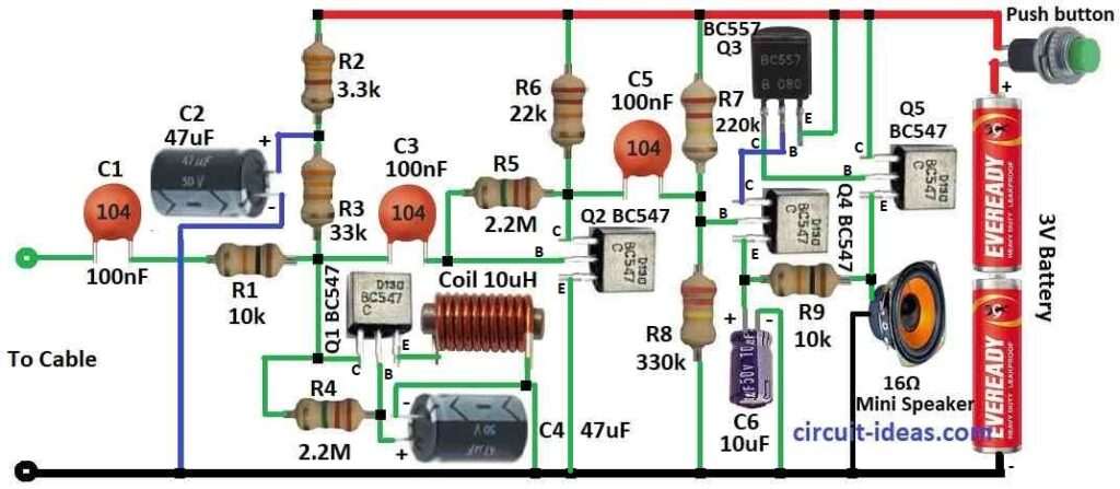
This is cable tracer receiver circuit and it works like this:
The coil picks up the signal from the transmitter and acts as an antenna.
In this circuit, a 10mH choke coil works well, although the design does not require an exact value; furthermore, increasing the number of windings generally improves signal reception.
Also, transistors Q1, Q2, Q3 make weak signal stronger and capacitor C4 and resistor R5 are high pass filter and they remove low noise and keep useful signal.
Q4 and Q5 are audio amplifier they make signal strong for speaker, so use small speaker (not 16Ω earpiece) for loud sound; also speaker gives tone and we follow tone to trace cable.
Extra Info:
Capacitors C1, C2, C3 and C5 act as bypass capacitors and help keep the voltage stable; additionally, resistors R1, R2, R4, R6, R7, R8, and R9 control the current and voltage levels in the transistors.
Furthermore, circuit uses low current of 50mA and we can use push button to turn it ON / OFF and this push button is power switch for receiver.
How to Build a Cable Tracer Receiver Circuit:
To build a Cable Tracer Receiver Circuit follow the below mentioned steps for connections:
- First, capacitor C1 goes to cable input through base of Q2.
- Next, Q1 collector connect to +V through R2 and R3 and resistor R4 goes between collector and base of Q1 and Q1 emitter goes to ground through 10uH coil.
- Now C4 positive side connect to Q1 base and negative side to ground.
- Then Q2 collector connect through R6, Q2 base connect in series: C3, R1 and C1 cable input and then Q2 emitter goes to ground.
- After that, Q3 collector connect to base of Q5, Q3 base connect to collector of Q4 and Q3 emitter goes to +V.
- Now Q4 collector connect to Q3 base, Q4 base connect through R7 and R8 from +V to –V and then Q4 emitter goes to ground through R9 and C6.
- Then Q5 collector goes to +V, Q5 base connect to Q3 collector and then Q5 emitter goes to ground through 16Ω mini speaker.
- Finally, push button connect to +3V battery as power switch.
Note:
- Making this circuits can be risky always follow safety rules, better to talk to expert before building if anyone do not know more about electronics
Conclusion:
To conclude, this Cable Tracer Circuit help find right wire in wall or bundle.
In addition, transmitter send signal in cable and receiver catch signal and make sound; hence the circuit is easy to use, low cost and is very useful for checking and tracing cables.
Leave a Reply