Making equipment simple helps to make and use easy and also is more reliable for sound boost, here, TDA2616 chip used for audio amplification.
Therefore, this chip is popular because it give good performance in small size, also this article show how to build simple Hi-Fi Amplifier Circuit using IC TDA2616 and with few parts which still gives good sound.
Hence, this circuit is good for audio lovers who want strong and simple Hi-Fi sound and also this post show how to set up amplifier with TDA2616.
Circuit Working:
Parts List:
| Components | Values | Quantity |
|---|---|---|
| Resistors | 8.2Ω 1/4 watt | 2 |
| Capacitors | Ceramic 220nF | 2 |
| Ceramic 22nF | 2 | |
| Ceramic 100nF | 1 | |
| Electrolytic 2200μF 50V | 2 | |
| Semiconductors | IC TDA2616 | 1 |
| Speakers 8Ω | 2 |
To begin with, small circuit size is good for portable power amplifier, as it gives 12W to 8 ohm speaker each side and uses +12V and -12V power.
Furthermore, TDA2616 is stereo power amp IC which come in 9-pin SIL9 plastic case, also made for main power devices like radios, tape players and TVs.
Moreover, it give same gain on both channels and follow Hi-Fi rules for IEC 268, DIN 45500 and it also have noise control to stop click sound when power is ON/OFF.
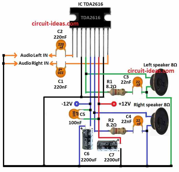
Pin 9 C1 goes to right audio input and pin 1 C2 to left input and then 220nF capacitors goes between inputs and block DC and only let AC sound pass.
After that, 22nF capacitors with 8.2Ω resistors R1, R2 connect to speakers at pin 4 at right and pin 6 at left and this help filter and makes sound clear.
Lastly, connect pin 5 to -12V and pin 7 to +12V, as these supply voltages allow the amplifier to operate correctly.
Formulas:
Some basic formulas help understand and use TDA2616 amplifier and these formulas help calculate how circuit works.
1. Output Power:
To find output power:
Pout = Vout² / RL
where,
- Pout is power in watts
- Vout is output voltage with peak to peak
- RL is speaker resistance in ohms
For 12W power to 8Ω speaker:
Vout = √(Pout × RL)
2. Capacitor Values for Filtering:
Output capacitors C3, C4 help clean signal to speakers and to find cutoff frequency:
fc = 1 / (2πRC)
where,
- fc is cutoff frequency
- R is resistance
- C is capacitance
Capacitors C6 and C7 keep power stable, as bigger capacitor means better filtering.
C = I / (f × Vripple)
where,
- I is current in amps
- f is ripple frequency
- Vripple allowed ripple voltage
Therefore, these help TDA2616 work smooth and give good sound.
How to Build:
To build a Hi-Fi Amplifier Circuit using IC TDA2616 follow the below mentioned steps for connections:
- First, gather all parts same as shown in circuit diagram.
- Next, pin 1 of TDA2616 goes to left audio in through capacitor C2 and other side of C2 goes to ground and then pin 9 goes to right audio in through capacitor C1 and other side of C1 goes to ground.
- After that, pin 3 and pin 8 connect to ground.
- Then pin 4 goes to one side of 8Ω left speaker through resistor R1 and capacitor C3 and other side to ground.
- Now pin 5 connect to -12V power through capacitor C6 and then pin 6 goes to one side of 8Ω right speaker through resistor R2 and capacitor C4 and other side goes to ground.
- Also, pin 7 connect to +12V power through capacitor C7 and then capacitor C5 connect between pin 5 and pin 7.
Conclusion:
To conclude, this simple Hi-Fi Amplifier Circuit using IC TDA2616 gives good sound in small setup, as this TDA2616 has inside parts like resistors, capacitors and output stage which is so easy to use.
Also, strong 8Ω speakers and good passive parts like ceramic and electrolytic capacitors give clean sound, so use 1/4 watt resistors and right parts to make amplifier work well.
Finally, it is good choice for DIY people who want cheap but powerful sound system.
Leave a Reply