In this post, we show how to make Simple Alcohol Detector Circuit using IC LM393, this circuit uses LEDs, resistors, capacitor, MQ-3 sensor and LM393 IC.
Alcohol detector find alcohol gas in air and give warning through light or sound.
Today, this article explains the MQ-3 sensor, the MQ-3 is a common alcohol sensor used in breath analyzers.
Also, the circuit work with 5V power like from USB charger or power supply.
Circuit Working:
Parts List:
| Components | Values | Quantity |
|---|---|---|
| Resistors | 5Ω 1 watt | 1 |
| 47k 1/4 watt | 1 | |
| 1k 1/4 watt | 2 | |
| Potentiometer 10k | 1 | |
| Capacitor | Ceramic 0.1µF | 1 |
| Semiconductors | IC LM393 | 1 |
| LED1 Trigger 5mm 20mA | 1 | |
| LED2 Power 5mm 20mA | 1 | |
| MQ-3 Gas Sensor | 1 |
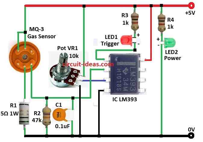
To begin with, this is a simple alcohol sensor module circuit shown in the diagram above.
First, the design uses only a few components, making it easy to build and then it is suitable for quick development and fast trial development.
The circuit uses LM393 op-amp which works with +5V and with low power and is good for small signal and 3.3V does not work well because MQ-3 sensor need 5V.
Op-amp job is to change analog signal to digital, so a 10k potentiometer is there to adjust sensor sensitivity.
There are two LEDs, with LED1 is trigger LED which turn ON when alcohol level is high and LED2 is power LED which turn ON when board gets power.
Finally, a capacitor reduces the noise in the circuit.
Formulas:
Here are simple formulas for basic alcohol detector using MQ-3 sensor, LEDs, resistors, capacitor and LM393 IC:
1. Voltage Divider Formula:
It sets the reference voltage (Vref) for the comparator.
Vref = Vin × VR1 / (R1 + VR1)
where,
- Vin is the 5V for supply voltage
- R1 and VR1 is the fixed resistor and a variable resistor
2. Comparator Threshold Voltage:
LM393 compare sensor output to Vref.
To get threshold voltage:
Vth = (Vout − VLED) / RLED
where,
- Vth is the voltage where comparator changes output
- Vout is the sensor output voltage
- VLED is the LED forward voltage
- RLED is the LED series resistor
3. LED Current Formula:
To find current in LED when comparator output is high:
ILED = (Vout − VLED) / RLED
where
- ILED is the current in LED
- Vout is the comparator output voltage
- VLED is the LED forward voltage
- RLED is the LED resistor
4. MQ-3 Sensor Alcohol Response:
Sensor output voltage shows alcohol level:
Calc ∝ 1 / (Vsensor)^n
where,
- Calc is the alcohol level
- Vsensor is the MQ-3 sensor voltage
- n is the constant which depends on sensor
Hence, these formulas help design and adjust the alcohol detector correctly.
How to Build:
To build a Simple Alcohol Detector Circuit using IC LM393 following are the steps for connections:
- First, gather all parts as from above circuit diagram.
- Next, connect LM393 pin 1 to LED1 and resistor R3 and to 5V power.
- After that, connect LM393 pin 2 to MQ-3 sensor output.
- Also, connect pin 2 to capacitor C1 and GND and add resistor R2 from pin 2 to GND.
- Then connect pin 3 to middle leg of VR1 pot, top leg to 5V and bottom to GND.
- Now connect pin 4 of LM393 to GND and connect pin 8 of LM393 to +5V supply.
- Further, connect one side of the MQ-3 sensor’s heater coil to GND through resistor R1 and connect the other side to +5V and next, connect either the A or B terminal of the sensor to +5V.
- Finally, connect resistor R4 and LED2 (power LED) from +5V to GND.
Testing:
- Power ON the circuit.
- Blow some alcohol vapor on MQ-3 sensor and if alcohol present then red LED (LED1) will turn ON.
Conclusion:
Overall, this easy to make Simple Alcohol Detector Circuit using IC LM393 uses simple parts, also it uses MQ-3 sensor and LM393 IC to detect alcohol in air.
Furthermore, we can use it for testing breath or checking environment.
Leave a Reply