30 Minutes Timer Circuit using CMOS IC 4011 is good for long time delay with few minutes to many hours.
This timer turns OFF device after 30 minutes.
It is useful for automation, delayed ON/OFF and save energy.
This type of circuit is good to save power.
Circuit use special chip called 4011 which is quad 2-input CMOS IC.
It has 4011 NAND gate, transistor, switch and relay for long timer.
We can use 9V battery or 12V power for easy to use anywhere.
Circuit Working:
Parts List:
| Component | Quantity |
|---|---|
| Resistors (All resistors are 1/4 watt unless specified) | |
| 10M | 1 |
| 4.7k | 1 |
| 1k | 1 |
| 10k | 1 |
| Capacitors | |
| Electrolytic 100µF 25V | 1 |
| Semiconductors | |
| CMOS IC 4011 | 1 |
| Transistor BC547 | 1 |
| Diode 1N4007 | 1 |
| LED 5mm 20mA | 1 |
| Relay 12V | 1 |
| Push Buttons | 2 |
When switch S1 is ON then capacitor C1 charges through resistor R1.
This charging change state of NAND gates.
When C1 voltage is high enough then NAND gates turn ON transistor Q1.
Q1 powers 12V relay.
Relay stay ON for time based on R1 and C1 values.
Main timing and switching done by 4011 CMOS IC which are 4 NAND gates.
BC547 transistor works as relay driver and 12V relay controls other devices.
Delay time is set by C1 220uF and R1 10M.
Diode D1 1N4007 protect from reverse voltage.
Push button S2 start timer and switch S1 stops it.
Formulas with Calculations:
To make our own timer circuit we need to use below formula:
T = 1.1 × R × C
where:
- R is 10M (10 × 10⁶ ohms)
- C is 100µF (100 × 10⁻⁶ farads)
So,
T = 1.1 × 10M × 100µF = 1100 sec = around 30 min
Change R1 or C1 to set different time.
How to Build:
To build a 30 Minutes Timer Circuit using CMOS IC 4011 follow the below mentioned steps for connections:
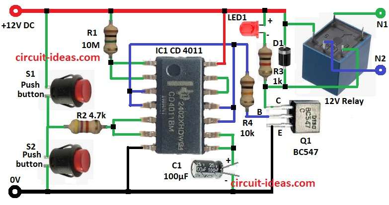
- Put all parts as shown in circuit diagram.
- Connect IC1 4011 pin 1 to pin 2 using resistor R1 and other end of R1 goes to +12V.
- Connect IC1 pins 3, 4, 10, 11 to base of transistor Q1 through resistor R4.
- Connect pins 5 and 6 of IC1 with resistor R2 and other end goes between push buttons S1 and S2.
- Connect pin 8 to pin 9.
- Connect pin 12 to pin 13.
- Connect pin 7 to GND and pin 14 to +12V.
- Connect LED1 and resistor R3 in series from Q1 collector to positive line.
- Connect relay coil between Q1 collector and positive line.
- Place diode D1 across relay coil as shown in diagram.
- Load and power supply go to N1 and N2 of relay.
- Transistor Q1 emitter goes to GND.
- Connect positive side of capacitor C1 to pins 8 and 9 and negative side to GND.
Conclusion:
This 30 Minutes Timer Circuit using CMOS IC 4011 is easy and good for long delay.
Change R and C to set different time.
IC 4011 keeps circuit working well and relay lets it control big devices.
Leave a Reply