This tutorial is about Motor Speed Regulator Circuit for PCB Drills, it control speed for clean and accurate holes.
Also, main part of the circuit is LM3578 IC with feedback and 1V reference and it also has oscillator.
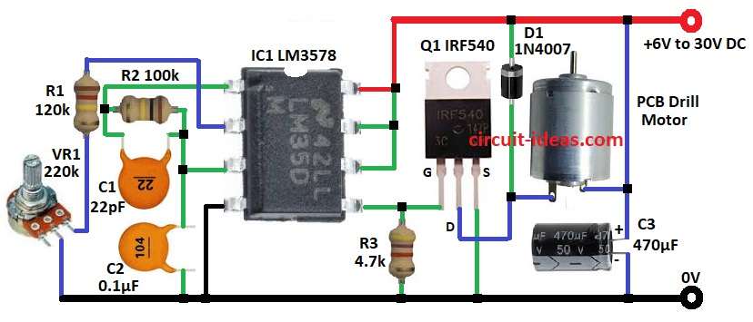
LM3578 and IRF540 MOSFET adjust motor speed and then they give smooth, adjustable speed for small PCB drills.
In addition, supply is from 6 to 30V DC but it should match the motor voltage.
Circuit Working:
Parts List:
| Components | Values | Quantity |
|---|---|---|
| Resistors (All resistors are 1/4 watt unless specified) | 120k | 1 |
| 100k | 1 | |
| 4.7k | 1 | |
| Potentiometer 220k | 1 | |
| Capacitors | Ceramic 22pF | 1 |
| Ceramic 0.1µF | 1 | |
| Electrolytic 470µF 50V | 1 | |
| Semiconductors | IC LM3578 | 1 |
| MOSFET IRF540 | 1 | |
| Diode 1N4007 | 1 | |
| PCB Drill Motor | 1 |
Circuit uses LM3578 switching regulator to make PWM for motor speed and MOSFET IRF540 works as switch and controls power to motor.
Furthermore, R1, R2, VR1 set reference voltage and work with C1 to set oscillator frequency and then C2 gives stability.
Then LM3578 IC makes PWM from feedback and IRF540 switches fast and controls motor power.
After that, D1 diode stops damage from back EMF and VR1 potentiometer lets us adjust motor speed.
Now C3 filters supply for smooth and reliable work and finally, R3 pulls MOSFET gate low when LM3578 output is low and avoids floating issues.
Formulas with Calculations:
Below are the formulas with calculations for Simple Motor Speed Regulator Circuit for PCB Drills:
Formula for LM3578 oscillation:
f = 1 / (R3 × C1 × 1.3)
here,
R3 = 100k and C1 = 22pF
f = 1 / (100k × 22pF × 1.3) = 348 kHz
The feedback sets the duty cycle and the resistor network controls the motor speed.
How to Build:
To build a Simple Motor Speed Regulator Circuit for PCB Drills follow the below connection steps:
- First, put all parts on PCB ad per diagram.
- Then pin 1 of IC to join of R2 end and C1 end.
- After that, pin 2 of IC goes to one end of R1 and other R1 end to VR1 and other VR1 end goes to GND.
- Now pin 3 of IC goes to other end of R2 and other end of C1.
- Also, C2 goes from pin 3 to GND and pin 4 of IC goes to GND.
- Next, pin 5 of IC connect to GATE of Q1 MOSFET and also R3 from pin5 go to GND which is pull-down.
- Further, pin 6,7,8 of IC go to +V of 6 to 30V DC.
- Then drill motor positive goes to +V, and motor other wire go to DRAIN of Q1.
- D1 diode from +V go to motor/Drain area which is protect from back EMF, and SOURCE of Q1 go to GND.
- C3 positive go to +V and C3 negative go to GND which is supply filter.
Conclusion:
To conclude, Motor Speed Regulator Circuit for PCB Drills are easy and simple and it uses LM3578 PWM and IRF540 switch.
The circuit smooth adjustable speed with low heat and is quite efficient and it picks supply voltage from 6 to 30V to match motor.
Leave a Reply