Inverter is a useful device in electronics.
It changes DC (Direct Current) to AC (Alternating Current).
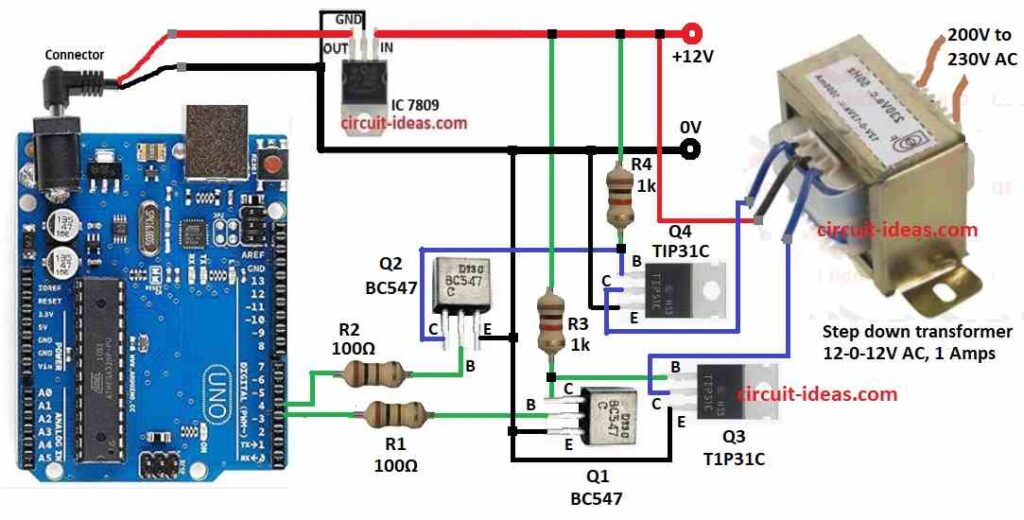
In this project for Arduino Based Power Inverter Circuit we will make simple inverter using Arduino.
It takes 12V DC and gives 230V AC.
We have used Arduino UNO, IC 7809, some transistors and a reverse transformer to get AC.
This circuit helps run small devices when power is gone.
Coding:
const int pin1 = 3; // Pin D3 connected to Q1
const int pin2 = 4; // Pin D4 connected to Q2

void setup() {
  pinMode(pin1, OUTPUT);
  pinMode(pin2, OUTPUT);
}

void loop() {
  digitalWrite(pin1, HIGH);
  digitalWrite(pin2, LOW);
  delay(10); // 50Hz frequency (20ms period, 10ms HIGH per side)

  digitalWrite(pin1, LOW);
  digitalWrite(pin2, HIGH);
  delay(10);
}
Code Explanation:
- Code sets pins D3 and D4 as output.
- In loop, Arduino makes D3 HIGH, D4 LOW, waits 10ms and then swaps with D3 LOW and D4 HIGH.
- This makes 50Hz square wave to drive transistors.
Parts List:
| Component | Quantity |
|---|---|
| Resistors | |
| 100Ω, 1k 1/4 watt | 2 each |
| Semiconductors | |
| Arduino UNO Board | 1 |
| IC 7809 | 1 |
| Transistors BC547, TIP31C | 2 each |
| Step down transformer 12-0-12V AC 1 Amps | 1 |
IC 7809 gives stable 9V to Arduino and control circuit.
This makes circuit work better.
Arduino sends square wave from pins D3 and D4.
When D3 is HIGH, D4 is LOW and opposite.
This makes pulses for transistors.
BC547 Q1 and Q2 boost weak signals from Arduino.
Then sends to TIP31C Q3 and Q4 power transistors.
R1 and R2 100Ω resistors protect BC547 by limiting base current.
TIP31C Q3 and Q4 act like switches.
They power the transformer one by one.
R3 and R4 1k resistors help TIP31C work properly.
Transformer is used in reverse and it takes 12V DC pulses and gives 230V AC output.
Formulas:
Here is the formula for frequency in this inverter circuit:
Frequency (ƒ) = 1 / Period
Total period = 10ms HIGH + 10ms LOW = 20ms
ƒ = 1 / 0.02s = 50Hz
Cautions:
- Use heat sink for TIP31C as they get hot.
- Add fuse or overcurrent protection for safety.
- Be careful as high voltage is risky and test the circuit with help from anyone if new with electronics.
How to Build:
To build a Arduino Based Power Inverter Circuit follow the below mentioned steps for connections:
- First collect all parts shown in circuit diagram.
- Give 12V DC to input pin of IC 7809.
- Connect GND pin of 7809 to circuit ground.
- Output pin of 7809 gives 9V and connect it to VIN pin of Arduino UNO.
- Connect D3 pin of Arduino to base of BC547 Q1 using 100Ω resistor R1.
- Connect D4 pin of Arduino to base of BC547 Q2 using 100Ω resistor R2.
- Connect emitters of Q1 and Q2 to ground.
- Connect collectors of Q1 and Q2 to base of TIP31C Q3 and Q4 through 1k resistors R3 and R4.
- Connect emitters of Q3 and Q4 to ground.
- Collectors of Q3 and Q4 goes to two ends of primary side of step down transformer.
- Connect center tap of transformers primary to 12V supply.
- Use a 12V to 230V step down transformer but in reverse.
- Secondary winding will now give 230V AC output.
Conclusion:
This small Arduino Based Power Inverter Circuit shows how to turn DC into AC using easy parts.
It is good for low power devices.
We can also upgrade it for better performance.
Leave a Reply