Imagine checking car wires without guessing or risk, then this Automotive Electrical Tester Circuit using 555 IC makes it possible, which shows polarity instantly with LED lights.
The circuit uses a 555 timer IC, so it becomes simple and is with low cost, also it can show positive or negative voltage by using two LEDs and because of this, it is useful for car wiring testing, battery checking and fault finding.
Also, circuit works fast and reliable and because of this, testing becomes simple and clear, so anyone can build and use it without difficulty.
Circuit Working:
Parts List:
| Components | Values | Quantity |
|---|---|---|
| Resistors (All resistors are 1/4 watt) | 22k | 3 |
| 270k, 620Ω | 1 each | |
| 120Ω | 2 | |
| Capacitor | Ceramic 0.47µF | 1 |
| Semiconductors | 555 Timer IC | 1 |
| Transistor PNP BC557 | 1 | |
| Transistor NPN BC547 | 1 | |
| LEDs Red and Green 5mm 20mA | 1 each | |
| Diode 1N4007 | 1 | |
| Probe Auto Tester | 1 | |
| Crocodile clips red and black | 1 each | |
| Power Supply 12V Car battery or DC supply | 1 |
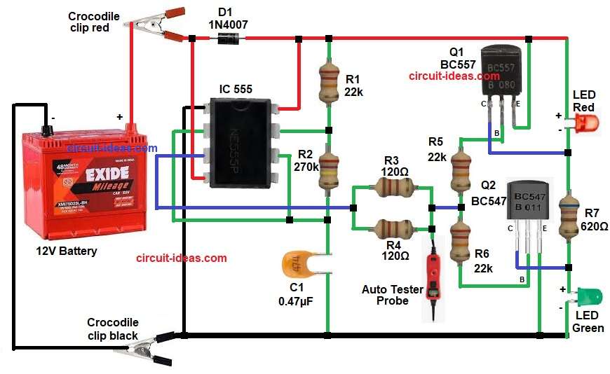
First, the battery gives 12V supply to the circuit, then diode D1 protects the circuit from wrong polarity connection and after that, resistor R1 and R2 with capacitor C1 make timing network for 555 IC.
Next, the 555 IC works in astable mode, so it generates square wave output continuously, because of this, the output at pin 3 goes HIGH and LOW again and again.
Then, this output goes through resistors R3 and R4 to the probe and when the probe touches any point, it senses voltage.
After that, transistors Q1 BC557 and BC547 control LEDs and i the probe gets positive voltage, then BC547 turns ON and so green LED glows.
But if the probe gets negative or reverse polarity, then BC557 turns ON and so red LED glows.
Also, resistors R5 and R6 limit base current of the transistors, and resistor R7 limits LED current, therefore, components stay safe.
Formulas with Calculations:
- Formula for 555 astable frequency:
f = 1.44 / ((R1 + 2R2) × C1)
where,
- f is the frequency
- 1.44 is the constant value for 555 timer
- R1 is the resistor connected between VCC and pin 7
- R2 is the resistor connected between pin 7 and pin 2/6
- C1 is the capacitor connected to pin 2/6 and ground
Now take values as in circuit:
R1 = 22k
R2 = 270k
C1 = 0.47µF
f = 1.44 / ((22000 + 2×270000) × 0.47×10⁻⁶)
f = 1.44 / (562000 × 0.47×10⁻⁶)
f = 1.44 / 0.26414
f = 5.45 Hz
So, our circuit gives around 5 Hz oscillation.
2. LED current calculation:
I = V / R
where,
- I is the current
- V is the voltage like 12V battery
- R is the resistance which is resistor value in ohms
For R7 = 620Ω and V = 12V
R = V / I
R = 12 / 0.02
R = 600Ω
So, in our circuit we have used standard resistor of 620Ω for our LED.
How to Build:
To build a Automotive Electrical Tester Circuit using 555 IC follow the below connection steps:
- Start, first to collect all the components like in above diagram.
- Next, take 555 IC and then connect pin 1 to ground.
- After that join pin 2 and pin 6 together and then connect capacitor C1 at this point and to ground.
- Then connect pin 3 to resistor R3 and R4 in parallel.
- Next, connect pin 4 to VCC +12V.
- Then connect pin 7 between resistor R1 and R2.
- Also, connect pin 8 to VCC +12V.
- Now connect R1 from VCC to pin 7.
- Then connect R2 from pin 7 to pin 2 and pin 6.
- After that connect capacitor C1 from pin 2/6 to ground.
- Next, connect diode D1 in series with positive supply for protection.
- Then connect R3 and R4 from pin 3 of IC to probe tester point.
- After that connect transistor BC557 Q1 and BC547 Q2 and then connect R5 and R6 to base pins.
- Now connect emitter of Q1 to positive supply and then connect its collector between cathode of red LED and resistor R7.
- Next, connect emitter of Q2 to ground and then connect its collector between resistor R7 and anode of green LED.
- Finally, connect resistor R7 in series with LEDs.
Conclusion:
So, this Automotive Electrical Tester Circuit using 555 IC gives simple and fast way to check polarity which works well in car electrical systems.
Because of low cost and easy design anyone can build it.
Moreover, it protects itself using diode and resistors and therefore, it becomes reliable tool for testing.