To begin with, Chirping Bird Sound Generator Circuit is simple electronic project which make sound like real bird chirping.
Moreover, it use basic parts like transistors, capacitors, resistors audio transformer to make natural bird type sound.
In addition, we can use this circuit in toys, doorbells and decoration items to make them more interesting and real looking.
Also, people use it for fun because it makes place feel like nature with bird sound.
Finally, this project helps us understand how sound works in electronics and we can also build it as a DIY project that makes learning fun and creative.
What is Chirping Bird Sound Generator Circuit:
Firstly, this small circuit make sound like real birds chirping and we can enjoy bird sound anytime and anywhere.
Moreover, many people use this circuit to make plastic birds look more real or make doorbell sound which is more nice.
In addition, it we have two astable multivibrator work together and they make warble sound like real bird singing
Finally, if we want nature sound in our life then keep reading and learn how this bird sound circuit work.
Circuit Working:
Parts List:
Resistors (All resistors are 1/4 watt)
| Values | Quantity |
|---|---|
| 1.5k | 4 |
| 2.2k | 3 |
| 68k | 2 |
| 10Ω | 1 |
| 1kΩ | 1 |
| Potentiometer 10k | 1 |
Capacitors:
| Types | Values | Quantity |
|---|---|---|
| Electrolytic | 10µF 25V | 3 |
| Electrolytic | 2000µF 25V | 1 |
| Ceramic | 47nF | 2 |
Semiconductors:
Other Components:
| Components | Quantity |
|---|---|
| Audio Output Transformer | 1 |
| 8Ω Speaker | 1 |
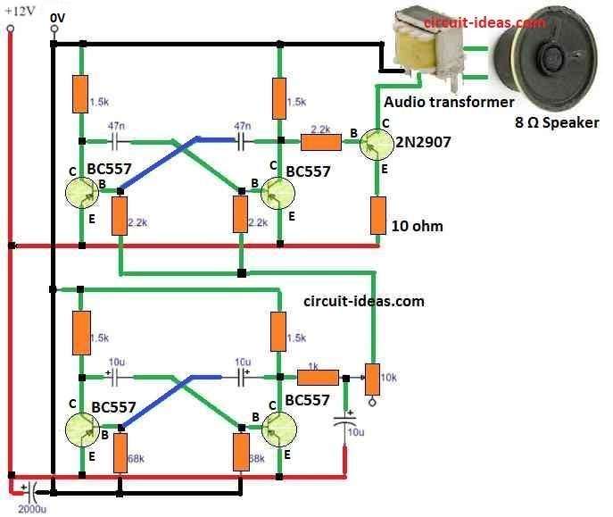
To begin with, this bird sound circuit uses two astable multivibrators, one make the bird tone and other make it repeat again and again.
Next, the first part is tone oscillator which makes the main bird sound, the tone change every half cycle.
Furthermore, we can change the sound by moving VR1 which is a variable resistor and the formula for tone generators is below.
Tone Formula:
Tone (f) = 0.693 / (R1 + 2 × (R2 + VR1)) × C1
here:
- f is tone frequency
- R1 is first resistor
- R2 is second resistor
- VR1 is variable resistor
- C1 is capacitor
Hence, to change the tone we need to use 10k variable resistor and 2.2k resistor in base, we can also change sound by changing capacitor between collector and base.
Also, second part control how fast chirp sound repeat and for that we can also use this below formula.
Repeat Rate Formula:
R = 0.693 / (R3 + R4) × C2
where:
- R3 and R4 are resistors
- C2 is capacitor
However, to make sound smooth a 10uF capacitor connects from potentiometer to ground and this shapes the square wave better.
Additionally, I added one more capacitor to create a special bird warble sound, which makes the sound last longer and feel more real.
Also, power supply changes tone a bit but we can fix that by changing VR1, in addition, even with different power voltages circuit will still work fine.
Moreover, we put a capacitor across the transformer to remove bad noise.
Lastly, this bird sound circuit work better and give more control than other complicated circuits like blocking oscillator.
Advantages and Disadvantages
Advantages:
- First, we can use this circuit in funny plastic birds, car horns and doorbells.
- Also, we can make different bird chirp sounds by changing tone and repeat speed.
- In addition, it is simple to use and works well with many power supply voltages.
- Moreover, it uses very few components, so the circuit is compact and reliable.
- Furthermore, we can use it in doorbells, plastic birds and alarm systems to make them more interesting.
- Finally, it is easy to modify, so we can change tone and speed to create different bird sounds.
Disadvantages:
- Moreover, sound is not 100% like real bird but just copy bird chirp in simple way.
- Furthermore, tone changes if power voltage changes and so we may need to adjust it time to time.
- Finally, it has limited sound options, so we cannot get many different bird sounds from the same circuit.
Conclusion:
Finally, everyone will enjoy using Chirping Bird Sound Generator Circuit in their electric projects, as we can use it for fun doorbell sound, cool car horn or make toy birds sound like real one.
Also, this circuit brings small nature sound into our daily life, as there is no need to worry try this fun project and enjoy bird chirping anytime!
Hence, if anyone have question or idea they can write in comment box, we are happy to help on our bird sound journey circuit!
Leave a Reply