Fire Alarm Circuit is very important for every home.
This small thing can save life because it tell early when fire is happening.
In this article we will learn how to make easy fire alarm circuit by yourself.
Good for small place like home, shop or small work area where there is no need of big system.
It is cheap and easy way to keep safe and protect things.
What is Fire Alarm Circuit:
Fire alarm circuit is one electronic system.
It see smoke, fire or heat and then give warning to people in building or area.
When fire happen people can go out safe and this alarm help to take fast action so fire does not make big damage.
Circuit Working:
Parts List:
| Components | Value | QTY |
| Resistors | 100k, 1k | 1 each |
| Variable Resistor Preset 500k | 1 | |
| Capacitors | Electrolytic 4.7µF 25V, 10µF 25V | 1 each |
| Semiconductors | Transistor BC117 | 1 |
| Transistors BC547 | 2 | |
| Relay 9V 400Ω | 1 | |
| Diode 1N4007 | 1 |
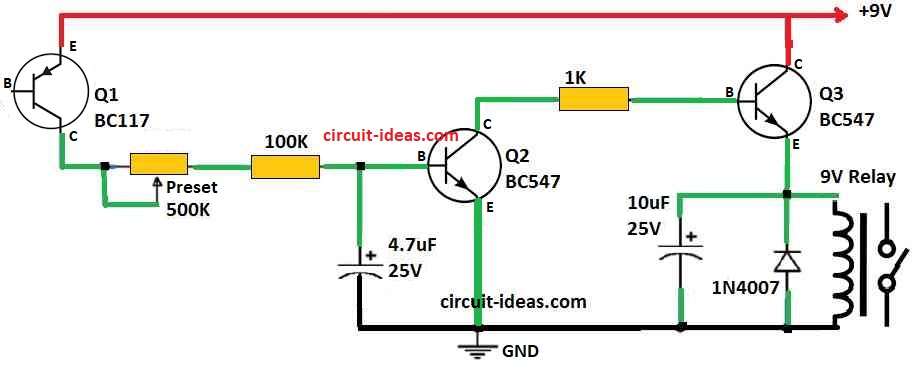
Main part of Simple Fire Alarm Circuit is BC117 transistor Q1 and it work like fire sensor.
Important thing is how heat and leakage voltage of transistor are connected.
When temperature goes up the leakage voltage also goes up.
This circuit uses that idea and when Q1 leakage become high it turn ON the transistor Q2.
Leakage Voltage (Vleakage) increases when Temperature increases.
Vleakage ∝ Temperature
When fire starts Q2 turn ON and then Q2 also turn ON Q3.
Q3 control the relay and relay can turn ON light, bell or horn.
So people can see or hear warning when fire happen.
Protecting the Circuit with Formulas:
When relay turn ON and OFF it make back EMF which can harm the circuit.
To stop this we need to use diode D1.
Diode D1 work like free wheeling diode.
It will help circuit live long and work good.
Back EMF Stopped by Diode D1 following are the formula to use:
VbackEMF = −L * di / dt
where:
- VbackEMF is bad voltage made for relay switch.
- L is coil inductance in relay.
- di/dt is how fast current change.
Temperature Adjustment and How It Work:
This Simple Fire Alarm Circuit let us change temperature using preset R1.
With this user can set when alarm should turn ON at certain temperature.
One thing to remember is this alarm is not latching so alarm stops when temperature go down under set level.
Set Temperature with R1 Preset:
Temperatureset = (R1resistance / R1totalresistance) * Temperaturemax
where:
- Temperatureset is the temperature when alarm start.
- R1resistance is resistance value we need to set.
- R1totalresistance is full value of R1.
- Temperaturemax is highest temperature allowed.
Relay is connected to the load using 3 pins: Common (C), Normally Closed (NC) and Normally Open (NO).
These work when alarm is ON.
Easy way to set temperature is with soldering iron and thermometer.
After turning ON the circuit put hot soldering iron near Q1 and keep thermometer close and then move R1 to set the right alarm temperature
Advantages and Disadvantages:
Advantages:
- This fire alarm circuit is very cheap and so many people can use it.
- It have easy design so even people with little electronic knowledge can make it.
- User can change the temperature when alarm should start.
- Relay help to turn ON warning devices so circuit work more reliable.
Disadvantages:
- Alarm can stop before fire danger is fully gone, because it turn off when temperature goes down.
How to Build:
Follow the below mentioned connection steps to make a Simple Fire Alarm Circuit:
- To begin look at the circuit diagram to see how parts connect and where they go.
- We can use this diagram many times while building the circuit.
- With help of diagram slowly place BC117 transistors Q1, Q2, Q3 the relay and diode D1 on the board.
- Use good wires and follow diagram to connect all parts together.
- Check all wires and be sure connection is correct and safe.
- Like said before use soldering iron and thermometer to set Preset R1 to right temperature.
- Then connect circuit to good power source.
- Switch it ON and test if it work proper.
Conclusion:
Simple fire alarm circuit can be made easy by anyone who like electronics and DIY work.
It is cheap and still work good for finding fire mostly in small places.
If anyone needs help or have question can write in comment section.
Do try this circuit for ones safety.