The IC 555 chip is very useful in many electronic works.
But this project is not same like normal timing circuits.
Here we making IC 555 Amplifier Circuit which uses microphone.
First microphone take the sound.
Then one small transistor give little power to sound like small switch.
At last IC 555 chip give more boost and make sound louder.
What is a IC 555 Amplifier Circuit:
We can use IC 555 like pulse width modulation or timer oscillator but people do not use it much as single amplifier.
Mostly IC 555 is used for timer and making pulses.
We can also set IC 555 like voltage comparator and make simple amplifier but it needs extra parts.
This way is not so popular because it does not use IC 555 for its main job.
Circuit Working:
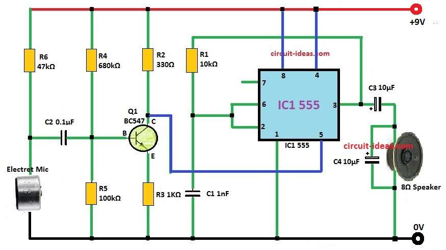
With 555 IC amplifier circuit we have talked before we can change design like in circuit diagram below if someone wants to use outside music signal.

Parts List:
| Category | Component | Quantity |
|---|---|---|
| Resistors (All resistors are 1/4 watt unless specified) | 10k CFR | 1 |
| 330Ω CFR | 1 | |
| 1k CFR | 1 | |
| 680k CFR | 1 | |
| 100k CFR | 1 | |
| 47k CFR | 1 | |
| Capacitors | 0.1μF | 1 |
| 10μF | 2 | |
| 1nF | 1 | |
| Semiconductors | Transistor BC547 | 1 |
| IC 555 | 1 | |
| Electret Microphone | 1 | |
| Speaker 8Ω | 1 |
To use 555 IC like amplifier we need special setup.
In this project we have used inside transistor to stop discharge work.
We have put IC in astable mode with no discharge pin.
Then control voltage pin (pin 5) take pre-amplified sound signal.
When we give outside voltage to control voltage pin it changes the inside reference voltage of 555 IC.
This outside voltage quickly change 555 IC timing and change output pulse width because it goes more than inside voltage divider level.
The timing of 555 IC is controlled nicely by giving outside voltage to CV pin and this changes threshold and trigger levels.
If no audio is coming then pin 5 is not getting voltage.
So 555 IC make very fast pulses which is more than 60 kHz and speaker cannot hear them.
When audio come in pin 5 gets voltage and then output pulse width keep changing.
Speaker can make this changing pulse into sound.
Important to know how electret mic works here.
Mic has one thin sheet diaphragm and one metal plate backplate with small air gap between and this gap act like insulator and make capacitor.
When sound hit diaphragm gap changes so capacitance also changes.
This change turn sound into electric audio signal.
But this audio signal is very small so we can use transistor BC547 to make it stronger first.
Formulas:
These formulas are used for astable multivibrator setup and it helps to make oscillation:
f = 1.44 / [(R1 + 2 × R2) × C]
where:
- f is how many times output square wave happen in 1 second Hz
- R1 and R2 are resistors in ohms Ω which are connected like in the circuit diagram
- C is capacitor in farads F which is also connected like shown in diagram
Pulse High Time (thigh):
thigh = 0.693 × R1 × C
where:
- thigh is how long the high part of wave stay in seconds
Note:
These formulas help us to start calculation when creating circuit like this.
How To build:
To build a IC 555 Amplifier Circuit follow the following steps for connection:
- Put 555 IC on the PCB.
- Connect pin 8 to PCBs positive power.
- Connect pin 1 to ground of PCB.
- Use resistor R1 to join pin 6 and pin 2.
- Connect pin 6 to pin 7.
- Put capacitor C1 between pin 6 and ground.
- Connect plus side of condenser mic to collector of BC547 transistor.
- Connect emitter of BC547 to ground.
- Use resistor R2 to connect base of BC547 to positive power.
- Join the point where R2 and base of BC547 meet to mic output.
- Connect pin 3 of 555 IC to plus side of speaker.
- Connect minus side of speaker to ground.
- Again connect pin 8 to positive and pin 1 to ground.
- Now give power to circuit.
- Talk into mic and listen sound from speaker.
Conclusion:
This new way of using IC 555 Amplifier Circuit which is interesting idea for changing and boosting sound signals.
With these building steps, people can understand and try this circuit and can be used for many sound-related projects.
Leave a Reply