Temperature sensing is very important in electronic systems because many devices use temperature sensors to check heat and protect the circuit from damage.
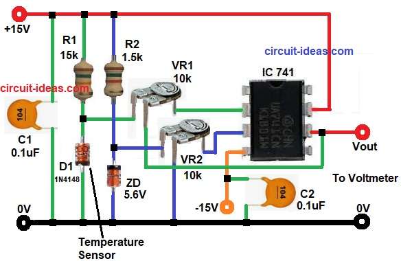
In this Op-Amp Based Diode Temperature Sensor Circuit, we used a simple 1N4148 diode as the sensing part and IC 741 as the signal processing unit.
The circuit gives output voltage which changes with temperature, so we can connect a voltmeter at the output and measure the temperature easily.
Also, this circuit uses very common components, so students and beginners can make it easily without much difficulty.
Here, the diode changes its forward voltage when temperature changes and the op-amp increases this small voltage change.
Circuit Working:
Parts List:
| Components | Values | Quantity |
|---|---|---|
| Resistors | 15k, 1.5k 1/4 watts | 1 each |
| Preset 10k | 2 | |
| Capacitors | Ceramic 0.1uF | 2 |
| Zener Diode 5.6V | 1 | |
| Diode 1N4148 | 1 | |
| IC 741 Op-Amp | 1 | |
| Power Supply +15V / -15V DC | 1 set | |
| DC Voltmeter | 1 |
Firstly, diode D1 works as temperature sensing element and when temperature increases, the forward voltage drop, across diode becomes lower.
Usually, silicon diode voltage decreases by around 2mV for every 1 degree Celsius temperature rise.
Next, resistor R1 gives bias current to the diode sensor and this current helps the diode work in forward bias condition.
After that, resistor R2 and Zener diode make a stable reference voltage and this reference voltage helps the op-amp compare the sensor voltage properly.
Then, VR1 and VR2 help for calibration and sensitivity adjustment, where we can use VR1 for zero setting and VR2 for gain or output voltage adjustment.
The IC 741 compares the voltage from the temperature sensing diode with the reference voltage and when temperature changes the diode voltage also changes, because of this, the output voltage at pin 6 also changes.
Therefore, when temperature increases the output voltage changes in proportional way and we can connect a voltmeter to read this voltage and convert it into temperature value.
How to Build:
To build a Op-Amp Based Diode Temperature Sensor Circuit follow the below connection steps:
- First, collect all components as shown in above circuit diagram.
- Next, place the IC on breadboard or PCB.
- Then connect IC pin 2 to middle pin of VR2 and IC pin 3 to middle pin of VR1.
- Next, connect IC pin 4 to -15V supply.
- Then take IC pin 6 as output and connect one end of voltmeter here and other end to ground.
- After that connect IC pin 7 to +15V supply.
- Next, connect resistor R1 and diode D1 from positive supply to ground.
- Then connect resistor R2 and Zener diode from positive supply to ground.
- After that take VR1 and connect upper pin between R2 and Zener diode, middle pin to IC pin 3 and lower pin to ground.
- Next, take VR2 and connect upper pin between R1 and D1 diode, middle pin to IC pin 2 and lower pin to IC pin 6.
- Then connect capacitor C1 from positive supply to ground.
- Lastly, connect capacitor C2 from IC pin 4 to ground.
Conclusion:
To conclude, this Op-Amp Based Diode Temperature Sensor Circuit gives a simple and low-cost way for temperature measurement.
The 1N4148 diode works as sensing element and IC 741 increases the voltage variation.
Also, the circuit uses easily available components and gives reliable analog output.
Therefore, it is a good project for students, hobbyists and basic industrial applications.
Leave a Reply