This 10 Watts MOSFET Audio Amplifier Circuit give about 10W power.
It good for playing sound on low impedance speaker.
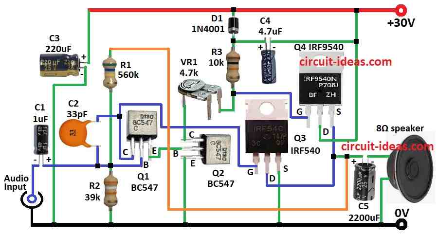
It use two BC547 transistors to drive signal and IRF540 with IRF9540 MOSFETs for output power.
BJT transistors make signal strong and MOSFETs give good power.
Together they work well for audio amp.
Circuit also use resistors, capacitors and one diode to keep sound good and works stable.
Circuit Working:
Parts List:
| Component | Value | Quantity |
|---|---|---|
| Resistors (All resistors are 1/4 watt unless specified) | ||
| 560 ohms | 1 | |
| 39k ohms | 1 | |
| 10k ohms | 1 | |
| Preset 4.7k ohms | 1 | |
| Capacitors | ||
| Ceramic 33pF | 1 | |
| Electrolytic 1μF 16V | 1 | |
| Electrolytic 220μF 50V | 1 | |
| Electrolytic 4.7μF 50V | 1 | |
| Electrolytic 2200μF 50V | 1 | |
| Semiconductors | ||
| MOSFET IRF540 | 1 | |
| MOSFET IRF9540 | 1 | |
| Transistor BC547 | 2 | |
| Diode 1N4001 | 1 | |
| Speaker 8Ω | 1 |
Capacitor C1 stop DC and passes only AC audio signal to transistor Q1 base.
Audio signal enter circuit through C1.
Q1 and Q2 work as Darlington pair and make preamplifier.
R1 give feedback and VR1 adjust idle (quiescent) current.
Capacitor C5 send output sound to speaker and also block DC.
C1 also connect to power filter capacitor C3.
Output MOSFETs are IRF540 Q3 and IRF9540 Q4.
Q3 N channel work for positive audio half and Q4 P channel work for negative half.
MOSFETs give strong signal by gate drive from Q1 and Q2.
Speaker 8 ohm connect between Q4 source and Q3 drain and gets louder sound.
Capacitors C3 and C4 clean power supply and remove noise.
Diode D1 protect from reverse voltage and makes circuit more safe.
So this circuit make clear and louder audio which is good for medium power use.
Formulas:
Below are basic formulas for 10W MOSFET audio amplifier:
1. Power Output (P):
P = VRMS² / Rload
where,
- VRMS is the voltage across speaker RMS
- Rload is the speaker resistance which is usually 8Ω
2. Bias Resistors (for Q1):
Q1 base voltage:
VB = VCC × R2 / (R1 + R2)
where,
- VCC is the power supply voltage
- R1 and R2 is the base bias resistors
3. MOSFET Current (ID):
ID = (VGS − Vth) / RDS(on)
where,
- VGS is the gate source voltage
- Vth is the threshold voltage of MOSFET
- RDS(on) is the resistance when MOSFET is ON
4. Capacitor Value for Coupling (C):
C = 1 / (2πfR)
where,
- f is the lowest frequency
- R is the load or next stage resistance
5. Voltage Drop in Filter Capacitor (Vdrop):
Vdrop = Iload / (f × C)
where,
- Iload is the current drawn
- f is the ripple frequency
- C is the filter capacitor value
These formulas help in design and working of amplifier circuit
How to Build:
To build a 10 Watts MOSFET Audio Amplifier Circuit follow the below mentioned connections steps:
- Take all parts like in the circuit diagram.
- Connect Q1 collector to gate of MOSFET Q3.
- Connect Q1 base to audio input through capacitor C1.
- Also connect resistor R1 and R2 in series to ground for bias.
- Connect Q1 emitter to Q2 base.
- Connect capacitor C2 one side to Q1 base and other side to Q1 collector.
- Connect Q2 collector to middle leg of VR1 and other leg of VR1 goes to positive supply through resistor R3 and diode D1.
- Connect Q2 base to Q1 emitter.
- Connect Q2 emitter to ground.
- Connect gate of Q3 to Q1 collector, drain of Q3 goes to source of Q4 and source of Q3 goes to ground.
- Connect gate of Q4 to point between VR1 2nd leg and resistor R3
- drain of Q4 goes to positive supply and source of Q4 to Q3 drain.
- Connect capacitor C4 from point between R3 and D1 to Q4 drain.
- Connect capacitor C5 to one side of 8Ω speaker and between Q3 drain and Q4 source and connect other side of speaker to ground.
Conclusion:
This 10 Watts MOSFET Audio Amplifier Circuit use both BJT transistors and MOSFETs gives good sound and medium power.
Proper biasing, coupling and filtering are important for best sound and working.
It is a simple and strong circuit to boost audio signal for many uses.