This post talks about 220V Temperature Controller Circuit in easy way, the circuit can turn ON or OFF heater, cooler or other things to keep same temperature.
Also, it uses big power like 220V and has sensor like thermometer to check heat or cold and also has small brain chip or timer to decide when to turn ON or OFF heater or cooler based on sensor.
At last switch part like triac sends power to heater or cooler.
Circuit Working:
Parts List:
| Components | Values | Quantity |
|---|---|---|
| Resistors | 6.8k 5W | 1 |
| 470k 1/4 watt | 1 | |
| 3.3k 1/4 watt | 1 | |
| 470Ω 1/4 watt | 1 | |
| Preset 2k | 1 | |
| NTC Thermistor 5k | 1 | |
| Capacitors | Ceramic 0.01µF | 1 |
| Electrolytic 220µF 25V | 1 | |
| Electrolytic 10µF 25V | 1 | |
| Semiconductors | IC 555 | 1 |
| Triac BT136 | 1 | |
| Zener diode 8.2V 1W | 1 | |
| Diode 1N4007 | 1 | |
| Socket for load | 1 | |
| Fuse 2A | 1 |
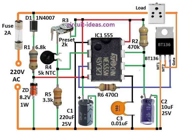
To begin with, we can make heat control circuit with 555 timer IC, one thermistor and some resistors; also a good thing about this circuit is it does not need perfect power supply.
Resistors are R3 adjustable and thermistor R4 and R5 and when thermistor feels cold below set point then voltage at pin 2 of 555 goes below 1/3 Vcc and also this turns heater ON with triac and starts timer.
If temperature goes hot before timer ends then heater turns OFF when timer ends and if not hot then heater stays ON.
Finally, we can use different thermistors, but their temperature characteristics must match the required temperature range.
WARNING: This circuit works with 220V main power, also electric shock are dangerous so only experts should handle!
Formulas:
This simple temperature controller uses a TRIAC and a 555 IC to control 220V AC power, as it turns the load on or off according to the temperature, which the NTC thermistor R4 monitors.
By changing ON and OFF time it tries to keep same temperature.
Thermistors are important part and they too feel hot or cold as their resistance change with temperature so circuit can know what to do.
Hence, there is one rule to follow the formula:
R3 + R4 = 2 × R5
where:
- R3 preset we can turn it to set what temperature we want.
- R4 is 5k NTC thermistor and it feel temperature.
- R5 give stable voltage to compare.
How to Build:
To build a 220V Temperature Controller Circuit we need to follow the below mentioned steps:
- First, use good 220V AC to 12V DC power supply for this circuit and be sure safety and isolation is okay.
- Next, put all parts on PCB like in circuit diagram and then connect power supply with correct + and – wires.
- Now use terminal blocks to connect heater and thermistor easy.
- Change R3, R4 and R5 to set temperature we want and also be sure triac has heat sink to stay cool.
- After that, test carefully and see the heater should turn ON/OFF when temperature change.
- Also, use good cover and wires to stop electric shock.
- Lastly, check circuit time to time for good working and safety.
Note:
- Warning working with 220V AC is very dangerous and if anyone do not know how to work with high voltage then ask help from expert person.
Conclusion:
Overall, a 220V Temperature Controller Circuit is useful and works good for many things, as it uses parts like thermistor, 555 IC and relay or triac to check and control temperature.
Furthermore, this circuit maintains the desired temperature by turning the heater or cooler ON and OFF.
We can also use it in industrial machinery and household appliances, such as ovens and air conditioners, where users need precise temperature control.
Therefore, it is safe and works well and helps save power too.
Leave a Reply