This Simple 220V White LED Flood Light Circuit is like a small power machine for big bright light, as it takes normal home current 220V and make those special white LEDs glow.
Also, the circuit works like converter and change big voltage to small one which are good for LEDs.
Inside small parts like resistors, capacitors and diodes, they work like tiny switch and storage for electricity.
All together they make strong white light come out and make place very bright.
But be careful working with 220V is not safe and do not try to build or fix these circuits if one is not having proper training or knowledge.
Circuit Working:
Parts List:
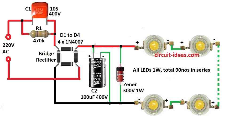
| Components | Values | Quantity |
|---|---|---|
| Resistor | 470k 1/4 watt | 1 |
| Capacitors | PPC 105 400V | 1 |
| Electrolytic 100µF 400V | 1 | |
| Semiconductors | Bridge Rectifier 1N4007 | 4 |
| Zener diode 300V 1W | 1 | |
| LEDs 3.3V 1W 300mA | 90 |
To begin with, this white LED floodlight make porch very bright with cool white light, as the circuit is very simple and save energy.
Furthermore, it connect straight to AC power with no need of big transformer.
Now ultra white LEDs take place of tube lights because they save power and are easy to use; also white LEDs give strong light from 10,000 to 60,000 MCD, and they work fine on 3V and 300mA.
LEDs come in spotlight and wide light type and their common size is 3mm, 5mm and 10mm; big power single white LEDs also one can find.
White LEDs first appeared in the 1990s, manufacturers make them with Indium Gallium Nitride, a blue LED chip and a white phosphor coating and the blue light from the chip hits the phosphor and produces white light.
Therefore, this circuit uses capacitor to drop high AC voltage to low and so that heat does not lose much power.
C1 drop voltage to around 100V and then D1 to D4 change AC to DC (rectifier) and C2 clean the DC and work like buffer.
Zener diode keep voltage at 69V and stop reverse voltage from hurting LEDs.
R1 is very important because it discharges the C1 capacitor after unplugging the circuit and without R1, C1 can keep more than 400V for a long time, which can cause a dangerous electric shock.
There are 90 LEDs in series which are bright like 100W CFL bulb, then put all circuit in safe box but remember do not touch.
One can put shiny reflector behind LEDs to make light spread more.
Important:
Do not touch or try to fix the circuit while it is connected to power.
Be careful as the circuit runs on AC power which is very dangerous and can give deadly shock if not handle right.
Please do not try to make this circuit if anyone is not sure how to work with high voltage.
Formula:
We can find the value of the AC capacitor using this formula:
Xc = 1 / (2πfC)
where,
- Xc means resistance in ohms Ω that capacitor gives to AC current.
- Capacitor are not like resistor.
- Resistor waste energy as heat.
- But capacitor store and release energy at every AC cycle.
Now breaking down the formula:
1 / (2πfC) this show how much capacitor stops the current.
2π is math number which is about 6.28.
f is frequency of AC, how many times current change direction in one second means in Hertz Hz.
C is value of capacitor in Farads F which tell how much energy capacitor can hold.
How it work:
When frequency (f) is high then current change direction fast.
Capacitor cannot store and release fast so Xc goes up with more resistance.
When capacitance C is big then capacitor can hold more energy, so Xc goes down with less resistance and current can flow easier.
So bigger capacitor = easier current flow and higher frequency = harder for capacitor to keep up.
How to Build:
To build a Simple 220V White LED Flood light Circuit follow the below steps for connections:
Safety First:
- First, always unplug circuit from power before touching or working on it and use tools with plastic handles and put circuit in shockproof box.
Circuit Design:
- Next, look at the circuit diagram to see where each wire and part connects.
Component Assembly:
- Then solder all parts like in the diagram and put 90 LEDs in series and then connect them to the rest of the circuit.
Rectification:
- After that, use 4 diodes D1 to D4 to make bridge rectifier which changes AC to DC and then add capacitor C2 to make DC smooth.
Voltage Regulation:
- Also, put Zener diode to keep voltage at 69V and stop reverse voltage from hurting LEDs.
Safety Resistor:
- Add resistor R1 to empty stored electricity from C1 after unplug this will stop shock risk.
Enclosure:
- Put whole circuit inside shockproof box and then one can add reflector behind LEDs to make light spread more like floodlight.
- Before plugging into power check all parts and wires again and then use multimeter to test and be sure everything is okay.
Connection:
- If all looks good then plug into mains and then watch the circuit and if anything strange happens then unplug right away.
Important Note:
- This is simple guide only, one needs to know about electronics and safety and if not sure better ask trained electrician for help.
Conclusion:
To conclude, Simple 220V White LED Flood Light Circuit change high AC power into bright light, as it gives strong and energy saving light, which is good for many uses.
Leave a Reply