To begin with, 3V to 24V Variable Power Supply Circuit is like a Swiss knife, where one supply does many things; just turn knob to change voltage from 3V to 24V.
Furthermore, this circuit is good for projects needing different voltage and hence, there is no need of many adapters, we just need to use this one.
Circuit Working:
Parts List:
| Components | Values | Quantity |
|---|---|---|
| Resistors | 3k 1/4 watt | 1 |
| 0.3Ω 5W | 1 | |
| 1k 1/4 watt | 1 | |
| Potentiometer 10k | 1 | |
| Capacitors | Electrolytic 2200µF 40V | 1 |
| Electrolytic 100µF 25V | 1 | |
| Semiconductors | IC LM1558 | 1 |
| Transistors 2N3055, 2N3053 | 1 each | |
| Transistor 2N3904 | 2 | |
| Diode 1N914 | 1 | |
| Bridge rectifier 6A4 | 4 | |
| Zener 6.2V | 1 | |
| Selector switch | 1 | |
| Fuse 2A | 1 | |
| Transformer 12-0-12V | 1 |
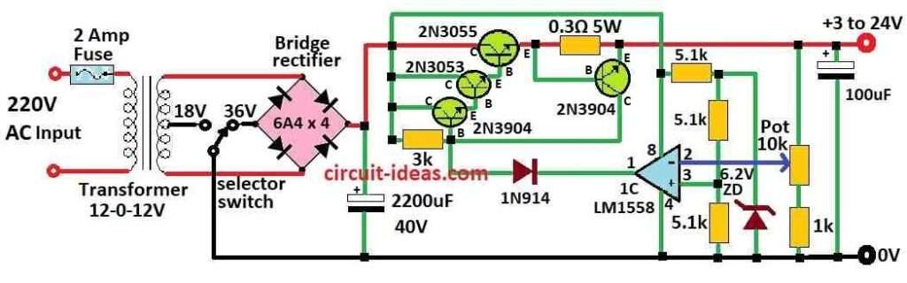
First, this above circuit can change power supply voltage from 3 to 25V and give 2 amps, it can give 3 amps or more if we use smaller 0.3 ohm resistor for current.
2N3055 and 2N3053 transistors need heatsinks and current resistor should be 3 watt or more.
Also, voltage control uses half of 1558 or 1458 op-amp, where 1458 max voltage is 36V and 1558 max is 44V.
Furthermore, keep pin 8 voltage under 30V with 6.2V Zener or 5.1k resistor.
Moreover, transformer must give enough current and voltage to about 4V which is more than output, which should not too high or op-amp gets too much voltage when load is low.
Finally, transformer here is center tap 25.2V AC 2 amp giving 24V at 0.7 amp, 15V at 2 amp and 6V at 3 amp and to get 3 amp output we can use center tap and set switch to 18V.
How to Build:
To build a 3V to 24V Variable Power Supply Circuit we need to follow the below mentioned connection steps:
- First, gather all the parts as per circuit diagram and then put 2N3055 and 2N3053 transistors on good heatsinks.
- Next, use 0.3 ohm resistor for current sensing and use half of op-amp 1458 or 1558 for voltage control.
- Then keep pin 8 voltage under 30V with 6.2V Zener or 5.1k resistor.
- Use 25.2V AC 2A center tap transformer and for 3A use center tap and switch at 18V.
- Now connect parts as circuit diagram make wires safe and strong and put all parts in place and test.
- After that, adjust voltage, current or parts if needed and work carefully solder in airflow and avoid short circuits.
Conclusion:
To conclude, 3V to 24V Variable Power Supply Circuit is very useful circuit, as it can give different voltage from 3V up to 24V.
Also, people use this in many electronics project where there is need of changeable power.
Leave a Reply