This article for 6V to 12V Converter Circuit (High Current) show how to make a helper circuit.
It takes 6V battery and give 12V power.
If we have motor or toy which needs 12V then this circuit can help make it work.
Thing that need more power can use this circuit which gives more current than some other converter.
Circuit Working:
Parts List:
| Component | Quantity |
|---|---|
| Resistors (All resistors are 1/4 watt unless specified) | |
| 390k | 1 |
| 2.2M | 1 |
| 180Ω | 1 |
| 68Ω | 1 |
| 680Ω | 1 |
| Capacitors | |
| Ceramic 0.1µF | 3 |
| Electrolytic 100µF 16V | 2 |
| Electrolytic 200µF 16V | 2 |
| Electrolytic 1000µF 16V | 2 |
| Electrolytic 1000µF 25V | 1 |
| Semiconductors | |
| IC TDA2003 | 2 |
| Transistors TIP36 | 1 |
| Transistors BD139 | 1 |
| Diodes 1N4002 | 3 |
| Zener diode 15V | 1 |
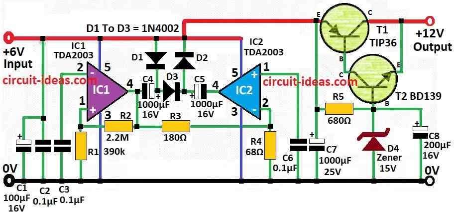
This voltage converter circuit uses one IC from SGS and some other small parts and it works between 6V and 12V.
Main IC used is TDA2003 but we can also use TDA2002 if we want.
Instead of changing full device to work with 6V this circuit is cheap and easy to build and that is why it useful.
This design does not use transformer as it is made simple and useful.
First IC (IC1) work like multivibrator and gives steady power.
Capacitor C3 control how fast it works.
When it is in standby it goes around 4 kHz an under load it goes to 7 kHz.
Second IC (IC2) give signal same like IC1 but in opposite phase.
Capacitor C4 charge through diode D1 and it charges up to power level minus little bit because of D1 drop when IC1 output is 0.
When IC1 output goes positive then voltage add to C4 and this stop D1 from working with no more conduction.
Then diode D2 charges capacitor C5 and this makes voltage goes double than power level.
So output voltage can go higher than input.
There is one limiter part also which uses 15V Zener diode and two transistors T1 and T2 in Darlington pair.
It stop voltage going too high when current is low.
This limiter keep output voltage around 14.2V.
Capacitor C8 is put at output side and it remove ripple and noise, so radio and audio stuff work better.
Transistors need extra heatsink so when making the circuit it is better to put both ICs on same heatsink close to PCB.
Also use bigger capacitors C4, C5, C6 of 2200uF to give more output current.
Formulas and Calculations:
We can use voltage doubler circuit to change 6V into 12V.
It uses capacitors and diodes in special way to make double voltage.
Voltage doubler output is about:
Vout = 2 × Vin − Vdiode
where:
- Vout is output voltage
- Vin is input voltage and in this circuit it is 6V
- Vdiode is voltage drop from diode
How to Build:
To build the 6V to 12V Converter Circuit (High Current) below mentioned are the steps to follow:
- Make or get PCB layout for the circuit.
- Mark all solder points and place where each part goes.
- Put IC TDA2003 or TDA2002 on same heatsink close to PCB.
- Fix transistors T1 and T2 which are the Darlington pair to other heatsink.
- Place capacitors C3, C4, C5, C6 and C8 in right place on PCB.
- Put diodes D1 and D2 same as in circuit diagram.
- Place 15V Zener diode in proper spot.
- Use circuit diagram and solder all parts on PCB one by one.
- Check carefully with no solder bridges and ensure all wires and legs connect are right.
- Check solder points for mistake or short circuit before adding the power.
- Give 6V to input side of the circuit.
- Use multimeter to check output voltage.
- It should be near 12V.
- If not working right then check for problem or change part values.
- After adding limiter be sure output voltage does not go above 14.2V.
Conclusion:
This 6V to 12V Converter Circuit (High Current)t give more power and can run things that need 12V.
It uses simple parts like IC, diodes, capacitors and work without transformer.
This circuit is good for motors, toys and other devices.
If made proper and test well it work strong and safe.
References:
Is it possible to convert 6V 4A (24W) DC to 12V 3A (36W) DC using step up booster?
Leave a Reply