Battery Status Indicator Circuit using Flashing LED is an easy to make project, as the circuit uses BC547 and BC557 transistor, some resistors, capacitors, one diode and one LED.
LED show battery condition by blinking light and it work with 6 to 12V battery and it is easy way to know battery health and it ensures it works well.
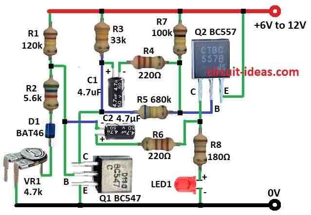
Circuit Working:
Parts List:
| Components | Quantity |
|---|---|
| Resistors (All resistors are 1/4 watt unless specified) | |
| 120k | 1 |
| 5.6k | 1 |
| 33k | 1 |
| 680k | 1 |
| 100k | 1 |
| 180Ω | 1 |
| 220Ω | 2 |
| Preset 4.7k | 1 |
| Capacitors | |
| Electrolytic 4.7μF 25V | 2 |
| Semiconductors | |
| Transistor BC547 | 1 |
| Transistor BC557 | 1 |
| Diode BAT46 (or any Schottky diode) | 1 |
| LED 5mm 20mA | 1 |
To begin with, LED keep blinking if battery voltage is above set level, also Q1 and Q2 transistors make one astable multivibrator circuit.
Furthermore, circuit works between 6V to 12V battery and preset VR1 can change the voltage level when LED stop blinking.
Also, blinking slow down when battery voltage goes near set level and LED stops when voltage goes below.
Finally, diode D1 used to fix temperature effect on Q1 base emitter voltage.
How to Build:
To build a Battery Status Indicator Circuit using Flashing LED follow the below mentioned steps for connections:
- First, gather all the parts as shown in the circuit diagram
- Join Q1 collector to Q2 base using resistor R5.
- Then C1 base connects between resistor R1 and R2.
- After that, Q1 emitter goes to ground.
- From positive supply to ground connect in line R1, R2, diode D1 and preset VR1.
- Now Q2 collector goes to ground through resistor R8 and LED1, Q2 base connect to Q1 collector and then Q2 emitter goes to positive supply from 6V to 12V.
- Also, put resistor R7 between Q2 base and resistor R5 and then put resistor R3 between Q1 collector and resistor R5.
- Lastly, capacitor C1 and resistor R4 goes between resistor R3 and R7 and also capacitor C2 and resistor R6 go between collector of Q1 and Q2 and resistor R8.
Conclusion:
To conclude, this simple Battery Status Indicator Circuit using Flashing LED check the battery level easily; also it warn when battery need charge or change.
Moreover, it is good for quick check and fits many electric projects because design is easy and simple to make.
Leave a Reply