Car Stereo Amplifier Circuit with IC TDA7297 is easy to build dual channel amplifier.
It works with one 12V power and gives good power to 8 ohm speaker.
With 17V it gives more power.
Its made for radios and TVs but can be uses for many things.
This circuit is good for audio system, midi system or strong portable speaker.
Circuit Working:
Parts List:
| Category | Description | Quantity |
|---|---|---|
| Resistors | 47k 1/4 watt | 4 |
| Capacitors | Ceramic 100nF | 1 |
| Electrolytic 1μF 25V | 2 | |
| Electrolytic 10μF 25V | 1 | |
| Electrolytic 1000μF 25V | 1 | |
| Semiconductors | IC TDA7297 | 1 |
| Power ON/OFF switch | 1 | |
| Woofer speaker 8Ω | 2 |
TDA7297 is very useful chip and can be used in many ways:
Many Uses:
- Work good in custom or new stereo system.
- Also is good for high end PC speaker and surround system.
- Work well in Bluetooth speaker, stereo or custom setup for better sound.
Good for Stereo:
- Better than small chips.
- Small and simple board.
- Can build on stripboard or veroboard.
4 Ohm Speakers:
- Can be used with 4 ohm speaker also but in our circuit we have used 8 ohm.
- Keep voltage under 14V for safety.
- Sound not as strong.
- For better sound with 4 ohm try STA540 or TDA7375.
Other Chip Choices:
- If only need mono sound with 1 speaker which is cheaper chips like TDA7266M or TDA7391 are good.
- Can use 1 channel of TDA7297 with just ground other input and leave other side empty.
Important About Bridging:
- Each speaker output already used 2 inside amps.
- Do not try to bridge again for more power.
- If it does not work right then both the sides do not match perfect.
More Power Ideas:
- Can get more power using same voltage.
- For mono and 2 ohm speaker try TDA7396.
- Another way is bi-amp which uses 2 speakers with active crossover filter.
- Split sound with high to one speaker and bass to other.
- Need crossover and extra speaker for this.
Formulas:
Basic Car Audio Amp with TDA7297
Power Formula:
With 12V power TDA7297 gives max 15W per channel to 8Ω speaker.
To find output power Pout use this formula:
Pout = Vcc² / (8 × RL)
where:
- Vcc is the power supply for 12V
- RL is the speaker for 8 ohm
This formula help us build simple car audio amp using TDA7297.
For more help check full datasheet or the sample circuits.
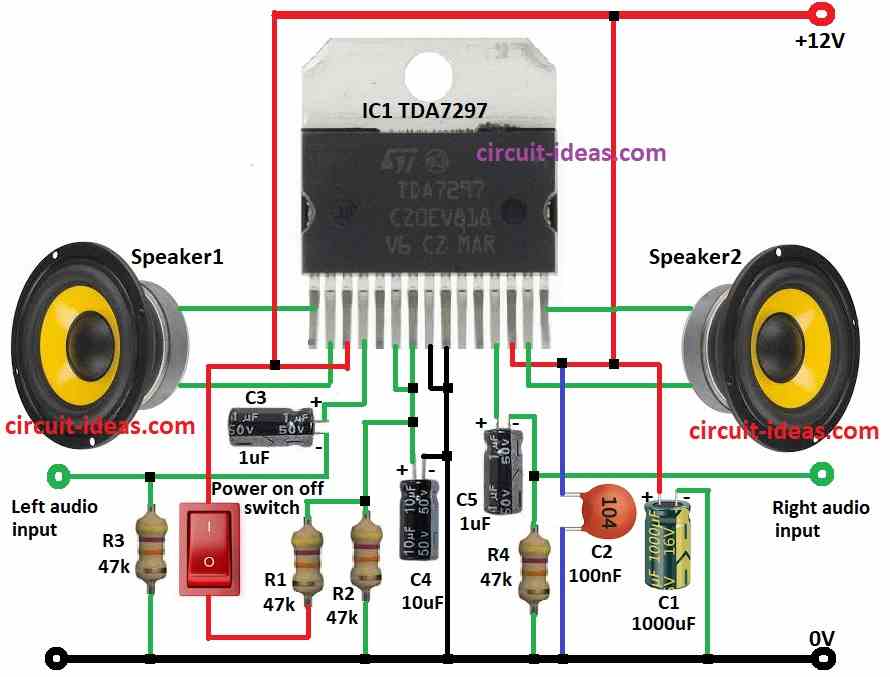
How to Build:
To build a Car Stereo Amplifier Circuit we need to follow the below mentioned steps:
- First collect all parts as per the circuit diagram.
- Connect pin 1 and pin 2 of TDA7297 to speaker 1.
- Connect pin 3 to 12V positive supply.
- Connect pin 4 to left audio input using capacitor C3.
- Add resistor R3 from left audio input to ground.
- Join pin 6 to pin 7.
- Connect pin 7 to ground using capacitor C4 and put resistor R2 between pin 7 and C4 to ground.
- Put power switch and resistor R1 in series between positive supply and resistor R2.
- Connect pin 8 and pin 9 to ground.
- Right audio input goes to pin 12 through capacitor C5 and resistor R4.
- Connect pin 12 to ground with same C5 and R4.
- Connect pin 13 to 12V positive and add capacitor C2 from 12V to ground.
- Connect pin 14 and pin 15 to speaker 2.
- Put capacitor C1 from 12V to ground.
Conclusion:
Car Stereo Amplifier Circuit with TDA7297 is a great chip!
Easy to use and works good with PC speaker, stereo or surround system.
No problem with normal 8Ω speakers.
Not best for very strong 4Ω speakers but other chips are better for that.
Follow correct voltage and it will work safe and strong.
Leave a Reply