This Continuity Tester Circuit uses two transistor like small switch for checking wire is good or bad.
We just need battery and one LED light.
One side touches to battery other side touches the wire.
If wire is okay, then current connects through and light will ON.
That mean electricity flows without stopping.
If wire is broken then no current flows and light stays OFF.
Made with normal parts this tester is easy and good to find wire problem.
What is a Continuity Tester Circuit:
Continuity tester circuit is a tool to check fast if circuit is still working or not.
It help to see if wire or line have break or full connection means electricity can flow.
We can check wire, cable, switch, fuse and other electric parts with this and if problem found we can fix it.
Circuit Working:
Parts List:
| Category | Item | Quantity |
|---|---|---|
| Resistors | 1k 1/4 W CFR | 1 |
| 100Ω 1/4 W CFR | 1 | |
| 1M 1/4 W CFR | 1 | |
| Capacitor | Ceramic 0.1µF | 1 |
| Semiconductors | Transistor BC557 | 1 |
| Transistor BC547 | 1 | |
| Red LED 20mA 5mm | 1 | |
| Coin Cell 3V | 1 |
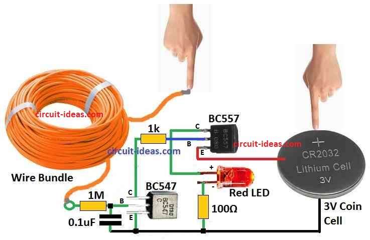
This circuit uses 3V battery for power.
BC547 transistor NPN emitter connects to ground.
BC557 transistor PNP emitter connects to battery positive side.
BC547 base connect to one probe for testing.
BC547 collector connect to BC557 base using one resistor.
NPN transistor like BC547 work like diode at base emitter and here it get power from probe side.
To test wire one probe touches wire and connect to BC547 base.
Other probe connects to positive of battery.
If wire is good with no breaks, current connects through wire and BC547 base emitter.
Then BC547 start working.
Current flow from BC547 collector to emitter.
This current connects to base of BC557 through resistor.
BC557 is PNP and it turn ON when base emitter is reverse.
So when wire is good BC547 let current flow and BC557 also turns ON.
BC557 collector connects to LED anode and cathode of LED connects to ground with resistor.
So when BC557 works current flow through LED and LED lights ON.
Formulas:
Using simple rule and small math we can choose right parts so tester circuit work good.
LED resistor (100Ω):
Use this formula:
R = (Vsource − VLED) / ILED
where:
- Vsource is battery and in circuit it is 3V
- VLED is LED voltage and red LED usually need 2V
- ILED is LED current and normal LED need 20mA
So:
R = (3V − 2V) / 0.02A = 1V / 0.02A = 50Ω
But we used 100Ω for safety, LED still lights but with less brightness.
Base resistor (1M) for BC547:
Use this formula:
R = (Vsource − VBE) / IB
where:
- Vsource is 3V battery
- VBE is 0.7V for BC547
- IB is base current
We want IB around 1/10 of LED current and if LED takes 20mA base current IB = 2mA
So:
R = (3V − 0.7V) / 0.002A = 2.3V / 0.002A = 1150Ω
But 1MΩ is used in this circuit is for low current test or safety.
Note:
Value of resistors can change depending on parts used like LED or transistor.
Formula help but actual testing and what parts we have also matter for final choice.
How to Build:
To build a Continuity Tester Circuit we can follow these steps.
- Put BC547 and BC557 transistors on the PCB.
- Connect BC547 emitter to ground line.
- Connect BC557 emitter to battery positive.
- Take probe 1 and connect it to base of BC547.
- Connect BC547 collector to base of BC557 using resistor R1.
- Now connect BC557 collector to LED anode positive leg.
- LED cathode negative leg connects to ground using resistor R2.
- Connect probe 2 to battery positive side.
Important Notes:
- Be sure all wires and parts connect in right place.
- After battery is added touch wire using two probes.
- If wire is good with no cut then LED will turn ON.
Remember:
- Resistor values may change if parts are different.
- Always check datasheet for LED and transistor to be sure it work well.
Conclusion:
To conclude this Continuity Tester Circuit check wire using BC547 NPN transistor.
If wire is good continuity found then current goes through BC547 and then through BC557 PNP transistor.
This turn ON LED to show wire is OK.
If wire is broken then no current flows and LED stay OFF.
Leave a Reply