Simple Counterfeit Money Detector Circuit is like smart light, it uses UV light to show secret mark on real note.
Furthermore, it also uses magnetic sensor to feel the special ink and sometimes it uses IR light to see real money pattern.
If the tool does not detect any special features, the note may be counterfeit; but however, this tool is not always accurate, so we should also examine the note ourself.
Circuit Working:
Parts List:
| Components | Values | Quantity |
|---|---|---|
| Resistors( All resistors are 1/4 watt unless specified) | 4.7Ω 1% | 1 |
| 100k | 1 | |
| Capacitors | Ceramic 0.47µF | 1 |
| Electrolytic 2.2µF 25V | 1 | |
| Semiconductors | IC LT1937 | 1 |
| Diode BAT85 | 1 | |
| UV LEDs 5mm 20mA | 4 | |
| Coil inductor 20uH | 1 | |
| Push on switch | 1 |
Today many fake money come because people use smart printer and bad people try to cheat, so finding fake money is very important.
Now many money counting machines can find fake notes so they use UV (ultraviolet) and MG (magnetic) check and these machines count many notes fast and check each note for magnetic things when note goes through the machine.
Hence, this way is very fast to know if note is fake or not.
Also, this article tells us how to make simple fake money detector at home using small UV light.
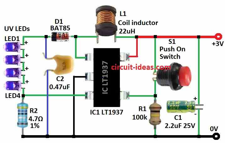
We do not use UV tube light here because this tube is weak and cost more so we use UV LED light which are small and strong; as this detector have two parts UV light and driver circuit.
UV LEDs are in clear tube or on small PCB board and we can make it how we like and UV LED need 3.6 volt to work so we use special circuit like step-up driver to give right power.
Moreover, this circuit uses LT1937 chip from company called Linear Technology and it gives same current to LEDs always and here, we have used LT1937 to power UV LED from 3V battery or power supply.
LT1937 work fast at 1.2MHz so it only needs few small parts and we have used LT1937ES5 LYTN in TSOT package for our test.
To keep LED safe we used 4.7 ohm resistor R2 to make current around 20mA and to protect ON / OFF button S1 we have put 100k resistor R1 to chips SHDN pin.
Finally, we also used one capacitor C1, 2.2uF with 6.3V to stop power noise and make circuit stable.
Formulas:
LT1937 is a small chip that work like DC to DC converter and it uses switching system to change power and to use this chip we need know some math formula and important points.
1. Output Voltage (Vout):
LT1937 uses two resistors to set output voltage and these resistors connect to FB pin.
The formula is:
Vout = Vref × (1 + Rtop / Rbot)
- Rtop is resistor from FB pin to Vout.
- Rbot is resistor from FB pin to ground.
- Vref is inside chip which mostly around 0.8V.
2. Switching Frequency (f):
We can set switching speed by adding resistor Rt from RT/CLK pin to ground.
Formula is:
f = 1600 / Rt
- Rt is in ohms
- f is in kHz or MHz depending on Rt value
3. Choosing Inductor (L):
Inductor is very important as it affects how good the circuit works and to find smallest value for inductor use:
Lmin ≥ (Vin − Vout) × Vout / (8 × f × Iout)
- Vin is the input voltage
- Vout is the output voltage
- f is the switching frequency
- Iout is the output current
4. Inductor Peak Current (Ipk):
We must know how much max current goes through inductor.
Formula:
Ipk = Iout × (1 + Vout / Vin)
This helps to choose inductor that does not break when high current goes inside.
5. Efficiency (η):
Efficiency shows how effectively the circuit converts power, while some power is lost as heat, switching losses and other factors.
Formula:
η = (Pout / Pin) × 100%
- Pout is the output power
- Pin is the input power
Note:
These formulas help design good circuit with LT1937 and we use them to pick correct resistor, capacitor, inductor and ensure circuit works good.
Always check LT1937 datasheet from Linear Technology which is now Analog Devices for full details and example circuits shown in the post.
How to Build:
To build a Simple Counterfeit Money Detector Circuit follow the below mentioned steps:
- First, follow the circuit diagram to join all parts.
- Next, fix 4 pieces of 5mm UV LED from LED1 to LED4 inside small clear tube or on small rectangle PCB or any way we like.
- Then use LT1937 chip in ThinSOT TSOT package and use LT1937ES5 LYTN version for testing.
- After that, give at least 3V DC power to the circuit and then check the circuit and put one money note under UV LED.
- Now if UV light show special marks on note then it is real money and if it is not working good then change LED place or make light stronger for better result.
- After everything works fine, put all parts inside box or case and it will protect and make it easy to carry.
- Lastly, do one final test and ensure detector is working correct.
- UV light can hurt do not look direct in light or touch too much.
Conclusion:
To conclude, Simple Counterfeit Money Detector Circuit is useful tool, as it uses UV light, magnetic and IR sensor to find real money signs.
Also, it help stop fake notes and protect money business.