Using popular IC 555 we can make Electronic Horn Circuit for cycle, alarm or fun use.
This Electronic Horn Circuit using IC 555 and one 8Ω speaker makes loud horn sound for car or alarm.
One 555 work as astable multivibrator which means it make square wave by switching high and low voltage again and again.
Sound pitch and loudness depend on how fast it switches ON and OFF (frequency and duty cycle).
Speaker connects to output and changes electric signal with the sound we can hear.
Circuit Working:
Parts List:
| Component Type | Description | Quantity |
|---|---|---|
| Resistors (All resistors are 1/4 watt unless specified | ||
| 220k | 1 | |
| 10k | 1 | |
| 100k | 1 | |
| Preset 1M | 2 | |
| Capacitors | ||
| Ceramic 0.1μF | 1 | |
| Ceramic 0.01μF | 1 | |
| Electrolytic 10μF 16V | 1 | |
| Semiconductors | ||
| IC 555 | 2 | |
| Speaker 8Ω | 1 | |
First 555 IC1 works like an oscillator and makes electric pulses again and again.
These pulses decide how fast or slow the sound repeats.
Resistor R3 and variable resistor VR2 connect to IC1.
Change VR2 to make pulse longer or shorter and this changes the sound pitch.
Second 555 IC2 make very fast pulses with high frequency.
This fast signal goes to speaker and make real sound.
So IC1 control speed of ON/OFF pulses and IC2 make fast wave for speaker.
By changing resistors we can control sound rhythm and pitch.
Formulas:
To make astable multivibrator horn with 555 IC we can use these formulas:
Frequency (f):
f = 1.44 / (R1 + 2 × R2) × C
This tell how fast 555 oscillate which means horn tone.
Duty Cycle (%):
Duty Cycle = (R1 + R2) / (R1 + 2 × R2) × 100%
This show how long output stay high or low with its change sound style.
Use this to design for horn circuit.
Change R1, R2 or C to get sound we like to change pitch, rhythm and loudness.
How to Build:
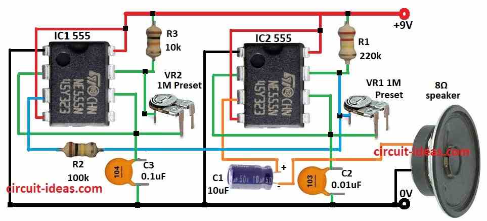
To build a Electronic Horn Circuit using IC 555 we need to follow the below mentioned steps for connections:
- Join all parts like in circuit diagram above.
- Pin 1 of IC1 connects to ground.
- Pin 2 connect to pin 6 of IC1.
- Pin 3 of IC1 connect to pin 7 of IC2 through R2.
- Pin 4 of IC1 connects to +9V.
- Pin 6 connect to pin 2 of IC1.
- Pin 7 of IC1 connects to +9V through R3.
- Pin 8 of IC1 connects to +9V.
- VR2 first leg connect to pin 7 of IC1 and second leg to pin 2 and 6 of IC1.
- Capacitor C3 connect to pin 2 and 6 of IC1.
- Pin 1 of IC2 connects to ground.
- Pin 2 connect to pin 6 of IC2.
- Pin 3 of IC2 connects to speaker through capacitor C1 and other end of speaker goes to ground.
- Pin 4 of IC2 connects to +9V.
- Pin 6 to pin 2 of IC2 connects through capacitor C2 and ground.
- Pin 7 of IC2 connects to +9V through R1.
- Pin 8 of IC2 connects to +9V.
Conclusion:
This Electronic Horn Circuit using IC 555 to make simple horn.
Change resistor values to control sound speed and pitch.
It is good for many uses like cycle horn, alarm or fun sound.
Leave a Reply