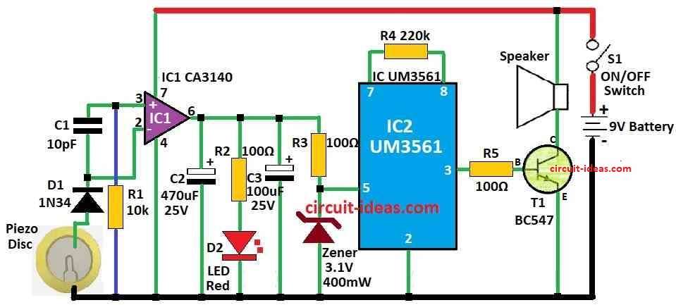
This Heat Sensor Circuit using Piezo Transducer is like small detective for heat.
It uses special thing called piezo transducer which work like tiny electricity maker.
When it get hot or cold it presses itself little bit and make small electric shock.
The circuit look at this shock to know how much hot or cold it is around.
Even a very small shock is very still enough for circuit to feel temperature change.
Circuit Working:

Parts List:
| Category | Description | Quantity |
|---|---|---|
| Resistors | 10k, 220k 1/4 watt | 1 each |
| 100Ω 1/4 watt | 3 | |
| Capacitors | Ceramic 10pF | 1 |
| Electrolytic 470µF 25V | 2 | |
| Electrolytic 100µF 25V | 2 | |
| Semiconductors | IC CA3140 | 1 |
| IC UM3561 | 1 | |
| Transistor BC547 | 1 | |
| Zener Diode 3.1V 400mW | 1 | |
| Diode 1N34 | 1 | |
| LED Red 5mm 20mA | 1 | |
| Piezo Disc | 1 | |
| Speaker | 1 | |
| ON/OFF Switch | 1 | |
| Battery 9V | 1 |
This is super sensitive heat sensor circuit for watching high heat in electronics.
Put inside devices that get hot nd works like fire alarm.
Uses piezo disc to feel heat by piezoelectric effect.
Piezo disc has special material with tiny crystals that make small electric signal when hot or pressed.
Strong op-amp IC CA3140 catches small signal from piezo disc.
Pins 2 and 3 connect with capacitor C1 to keep balance.
If no heat then output is low and if hot then output goes high to give signal.
High output turns ON alarm with ROM IC UM3561.
UM3561 makes fire engine sound from pin 6 which is not connected.
It needs 3V power so Zener diode changes from 9V to 3V.
Resistor R4 220k helps ROM chip work right.
Signal from IC2 is weak so transistor T1 makes sound loud to speaker.
Capacitors C2 and C3 keep voltage steady for IC2.
Put piezo disc on metal part near heat like heat sink.
No setting needed so use 9V to 12V DC power from device.
Formula:
CA3140 is a BiMOS op-amp.
That means it mixes two things: bipolar transistor and MOSFET.
Because it have very high input resistance and a very low input current and also work fast, people use it in many different circuits.
Simple Op Amp Formula:
Even if CA3140 have special features it still work like normal op-amp.
One important rule which is the golden rule for op-amp is this formula:
Vout = Aol × (V+ – V-)
where:
- Vout is output voltage.
- Aol is open loop gain and this value is very big in good op-amps.
- V+ is input voltage on non-inverting pin.
- V- is input voltage on inverting pin.
When we use CA3140 in some circuit this formula help to understand how it work.
How to Build:
To build a Heat Sensor Circuit using Piezo Transducer follow the below mentioned assembling steps:
- Put lead zirconate on middle part of piezo disc.
- Join pin 2 inverting and pin 3 non-inverting of CA3140 using capacitor C1.
- Connect output of piezo disc to input pins of op-amp IC.
- Take output from IC1 and connect to UM3561 ROM IC.
- Set alarm sound by connecting pin 3 the right way.
- Use Zener diode to drop voltage to 3V for UM3561.
- Connect resistor R4 to control ROM IC sound speed.
- Use BC547 transistor T1 to make speaker sound louder.
- Add capacitors C2 and C3 to keep voltage steady for IC2.
- Stick the thin side of piezo disc on metal body of machine, near heat sink or hot part.
- Give 9 to 12V DC power where we can take this power from the same machine.
- Be safe before giving power and check all wire and parts are in right place and tigh
Conclusion:
To conclude this Heat Sensor Circuit using Piezo Transducer is easy and works good to find temperature change.
It uses piezoelectric property of special material to turn heat change into small electric signal.
This signal can connect with a alarm or other system to give warning or action.
Leave a Reply