In electronics, a small audio amplifier can improve sound quality for many applications, also this Simple Mini Audio Amplifier Circuit uses the TDA7052 IC, and the diagram below shows its design.
Moreover, it needs few parts and easy to build and is good for better sound in small projects; also this circuit is very good for DIY and hobby people which is easy and works well.
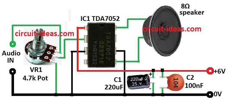
Circuit Working:
Parts List:
| Components | Values | Quantity |
|---|---|---|
| Resistor | Potentiometer 4.7k | 1 |
| Capacitors | Electrolytic 220µF 25V | 1 |
| Ceramic 100nF | 1 | |
| Semiconductors | IC TDA7052 | 1 |
| Output 8Ω Speaker | 1 |
This low-noise audio amplifier provides small-power amplification for compact applications; furthermore, the TDA7052 IC serves as the main component because it is easy to use, fits into a small space and integrates all the necessary circuitry inside the chip.
First, audio signal comes from one input like phone or music player and then it goes to the TDA7052 IC and then IC makes sound louder.
In addition , the circuit works with 6V power from battery or power adapter and we can control sound level using VR1 4.7k potentiometer which changes input signal level.
Also, capacitors C1 and C2 help remove noise and keep sound clear and then the loud signal goes to 8Ω speaker to play sound.
Formulas:
To make and understand TDA7052 mini audio amplifier we can use some basic formulas.
Power Calculation:
To find power of amplifier:
P = Vout² / Rload
where,
- P is the power in watts
- Vout is the output voltage in volts
- Rload is the speaker resistance in ohms
For 8Ω speaker:
P = Vout² / 8
TDA7052 has fixed gain and if using adjustable gain amplifier then use this formula:
Gain = Vout / Vin
where,
- Vout is the output voltage
- Vin is the input voltage
This does not apply for TDA7052 since gain is built-in.
Capacitor C2 is 100nF which is the Coupling Capacitor:
Cutoff frequency (fc) = 1 / (2π × Rload × C)
where,
- fc is the cutoff frequency in Hz
- Rload is the speaker resistance
- C is the capacitance in farads
Capacitor C1 220µF is the Filter Capacitor:
- C1 used for power noise filter and stable voltage.
Ripple voltage (Vr) = Iload / (f × C)
where,
- Vr is the ripple voltage in volts
- Iload the current used amps
- f is the frequency in Hz
- C is the capacitance in farads
These formulas help us understand how amplifier works, as power depends on voltage output and speaker ohms.
How to Build:
To build a Simple Mini Audio Amplifier Circuit using IC TDA7052 follow the below mentioned connections steps:
- First, collect all parts as shown in the circuit diagram.
- Next, connect pin 1 of IC1 TDA7052 to +6V power.
- After that, connect pin 2 of IC1 to middle leg of VR1 4.7k potentiometer.
- Then first leg of VR1 goes to audio input and third leg goes to ground.
- Now, connect pin 3 and pin 6 of IC1 to ground and then connect pin 5 of IC1 to one wire of 8Ω speaker.
- Finally, connect pin 8 to other wire of 8Ω speaker and then put C1 and C2 capacitors between +6V and ground.
Conclusion:
Overall, this Simple Mini Audio Amplifier Circuit using IC TDA7052 is easy and cheap project; it uses TDA7052 IC to build small but good mini audio amplifier.
Also, it requires few parts, easy to make and is good for small audio work.
Leave a Reply