Our device is safe from bad voltage by using this Simple Over Voltage and Reverse Voltage Protection Circuit, as this circuit uses P channel MOSFET FQP47P06 which better than only diode.
Furthermore, simple diode can stop reverse voltage but not protect from overvoltage or surge, but here the MOSFET and Zener diode give protection.
Circuit Working:
Parts List:
| Components | Values | Quantity |
|---|---|---|
| Resistor | 100k 1/4 watt | 1 |
| Semiconductors | MOSFET P-Channel FQP47P06 | 1 |
| Zener diode 9V | 1 |
To begin with, this circuit is easy way to protect our device from high voltage and wrong power and it needs only three main parts.
P-Channel MOSFET FQP47P06:
Works like smart switch and control current of our device as it is strong and can handle voltage over 60V and is good for reverse voltage protection.
Resistor R1:
Small part control current going through Zener diode.
Zener Diode 9V:
Keep voltage safe for our device and also stays OFF in normal voltage and when voltage goes too high it turns ON and send extra current away from MOSFET to protect it.
How Circuit Work:
When the power supply has the correct polarity, the MOSFET allows current to flow to the device and the Zener diode behaves like a normal diode.
Reverse Voltage Protection:
If we connect the power supply incorrectly, the MOSFET blocks the current and protects the device.
Overvoltage Protection:
If voltage is too high then Zener diode send extra current out and keep voltage safe for our device.
Formulas:
To make overvoltage and reverse voltage protection circuit using P-Channel MOSFET (FQP47P06), resistor and Zener diode we used these important things:
Gate Resistor (Rgate):
Normal value is between 10kΩ to 100kΩ, so choose value by looking at max gate source voltage (VGS) and gate capacitance (Cgs).
Use this formula:
Rgate = (Vin_max − VGS(th)) / Igate
where,
- VGS(th) is gate threshold voltage which is negative for P-MOSFET.
- Igate current needed to turn ON the MOSFET.
Note:
Change part values based on our circuit power and how much voltage protection we need and by using FQP47P06, resistor and Zener diode we can make good and simple protection circuit.
How to Build:
To build a Simple Over Voltage and Reverse Voltage Protection Circuit follow the steps mentioned below for connections:
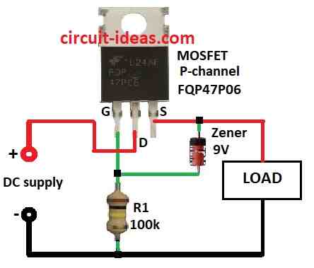
- First, get all parts as per the circuit diagram above.
- Next, connect MOSFET gate to ground with R1 resistor, connect MOSFET drain to +DC supply and then connect MOSFET source to load.
- After that, connect Zener diode anode to MOSFET gate and cathode to MOSFET source.
- Lastly, connect load between MOSFET source and ground.
Safety Tips:
- Ask help from expert if anyone is new and one should know part limits like voltage and current.
- Check all wires and pins two times and then first test with low voltage power.
Conclusion:
To conclude, this Simple Over Voltage and Reverse Voltage Protection Circuit is a 3 part protective device from reverse and over voltage.
Also, it is an easy design but very useful to save electronics, but always follow safety when build or use the circuit.
Leave a Reply