This Touch Controlled Potentiometer Circuit one just need to tap it and it will start to work.
No need to turn knob or move the slider it just touches the sensor and it changes the resistance or voltage.
It uses capacitive sensing which means that when one contacts it, the body will act as a switch.
So cool no?
Circuit Working:
Parts List:
| Component | Quantity |
|---|---|
| Resistors (1/4 watt) | |
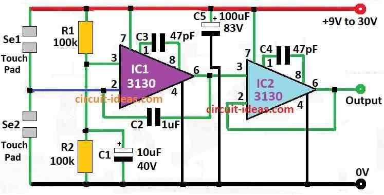
| 100k | 2 |
| Capacitors | |
| Ceramic 1µF | 1 |
| Ceramic 47pF | 2 |
| Electrolytic 10µF 40V | 2 |
| Electrolytic 100µF 83V | 2 |
| Semiconductors | |
| IC 3130 | 2 |
| Touch Pads (pairs) | 2 pairs |
This touch potentiometer circuit uses IC1 CA3130 which is a op-amp with very high input impedance.
When finger touch sensor Se1 capacitor C2 MKT type get charged through skin.
This make IC1 output voltage go down slowly to zero.
If the touch sensor Se2 is used instead opposite thing happen like voltage will go up slowly until same as power supply.
After finger is removed output voltage stay same because C2 hold the charge.
But slowly slowly voltage drops to about 2% every hour.
This kind of touch potentiometer is useful in many things where need of a potentiometer that work by voltage but not by hand turning.
If someone does not want touch sensor then a normal switch or button can be used just to put 1M resistor in line like mentioned in circuit diagram.
Formula:
This touch control potentiometer circuit works using capacitive sensing and feedback.
To understand when comparator changes its output from high to low, or low to high then we need to know voltage level where this will happen.
Comparator check difference between sensor voltage and a set reference voltage.
Lets say:
- Vcap is the voltage from capacitive sensor circuit
- Vref is the reference voltage which connects to comparators non-inverting input
When Vcap become same as Vref then comparator changes output.
So we say:
Vcap = Vref
This is point where switching happen.
Exact behavior like how fast it will switch or if small delay is there depend on comparator IC used.
Datasheet of IC will give that information about hysteresis, speed etc.
If IC 3130 is name of special or unknown chip then please give more details or datasheet so one can understand better.
How to Build:
Below mentioned are the steps to build a Touch Controlled Potentiometer Circuit:
Keep all parts ready:
- Take all parts that are needed and check if they work good.
Plan circuit design:
- Think where each part is going to be connected and make a design about it connections
- We can look at given diagram or make own from these steps.
Put IC1 CA 3130 in place:
- Put the op-amp on breadboard or PCB.
- Connect power pins V+ and V– to right voltage.
- Then connect output pin to other parts in circuit.
Add capacitor C2:
- Place the MKT type capacitor on board.
- Connect it to right pins of op-amp.
- Check if capacitor has polarity and if yes then connect correct way.
Connect touch sensors:
- If using touch sensor connect it to right input pin of op-amp.
- If using switch or button follow instruction like put 1M resistor in series.
Add resistors:
- Put the resistors where needed like shown in diagram.
Power the circuit:
- Give power to circuit and check positive and negative go correct way.
Test the circuit:
- Before fixing parts permanently, test it.
- Check that the output voltage changes correctly by touching the sensor or pressing the button.
Finish build:
- If circuit works fine fix all parts in place.
- Clean up loose wires.
Optional:
- If required then put circuit inside a box for protection or connect it with bigger project.
Note:
- Always check twice for all wires and parts before turning ON the circuit.
- If it does not works then check again its wiring and part values to find a problems solution.
Conclusion:
This Touch Controlled Potentiometer Circuit is easy and smart way for people to use electronics.
It helps a lot when space is small or place not good for normal knobs or buttons.
These circuits are used in many things like home gadgets, factory machines and human computer systems.
Leave a Reply