This article show how to make small and Simple Transformerless Power Supply Circuit which changes big voltage from wall socket to small voltage for electronics.
Also, this circuit does this in smart way with no need of big transformer.
WARNING: High voltage is dangerous, so only make this when adult is there and watching.
What is a Transformerless Power Supply:
Transformerless power supply is power source with no need of normal transformer.
Furthermore, normal transformer help to separate input and output and also control voltage in regular power supply, but transformerless circuit there is no use of transformer, it make circuit small and cheap.
What is Transformerless Power Supply:
Like name say this circuit does not uses transformer or inductor, it take high voltage AC from wall and make it low DC.
Idea is simple like put big capacitor like 205 to 400V in line with input wire and this capacitor will help to drop voltage to safe level for using in electronic circuit.
Parts Details:
To work safe capacitor voltage rating must be more than peak voltage of AC from wall, for example this type of circuit uses 2uF 400V capacitor.
Voltage stays the same but capacitor limits the AC current because of its reactance.
Handling Voltage Peaks:
Sometimes voltage goes too high, so to stop this we should add a Zener diode after the bridge rectifier.
Moreover, the Zener diode power rating must match the current from the capacitor, because this helps keep the voltage safe and the circuit works properly.
Important to Know:
Also, this power circuit is only for small circuits an we must put it in strong plastic or insulated box for safety.
This type of circuit is not good for using with outside devices or as general AC to DC converter.
Good Things (Advantages):
For low power jobs, this circuit is cheap and works well and if we need less than 100mA current, it can replace a big transformer.
Bad Things (Disadvantages):
But the circuit also have problems:
Circuit can not give big current, also if we touch open parts or use metal box it is very risky because there is no separation from high voltage AC.
As a result, circuit make voltage spikes and this can damage both the power supply and the device we have connected.
Circuit Working:
Parts List:
| Components | Values | Quantity |
|---|---|---|
| Resistors | 1M 1/4 W | 1 |
| 22Ω 1W | 1 | |
| Thermistor (NTC) 5D-11 | 1 | |
| Capacitors | PPC 2µF 400V | 1 |
| Electrolytic 1000µF 25V | 1 | |
| Semiconductors | Diode 1N4007 | 5 |
| Zener 12V 1W | 1 |
How Transformerless Power Supply Works:
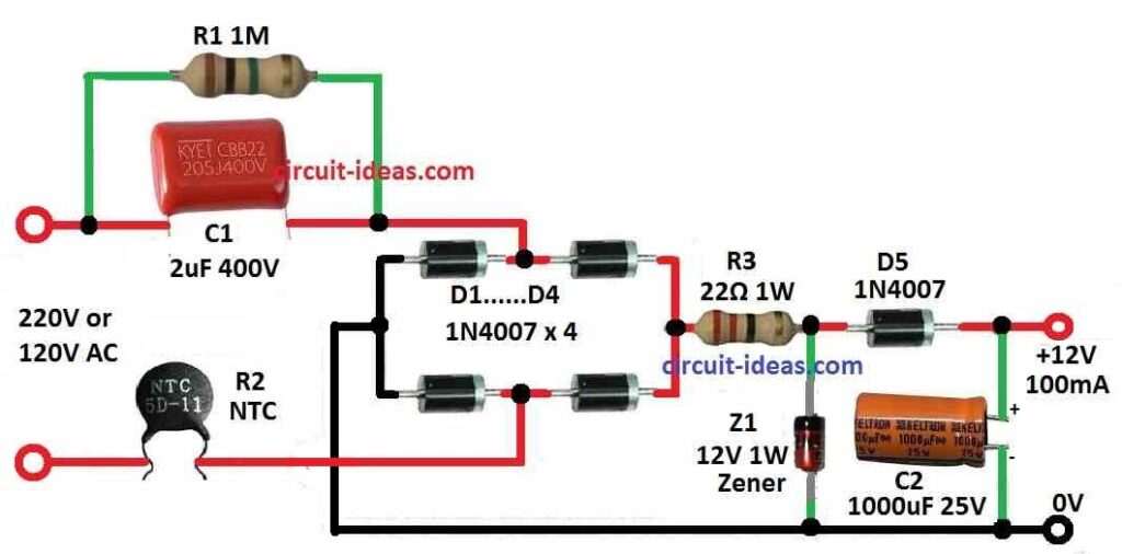
In this circuit capacitor C1 stop too much current from wall but full voltage still goes to bridge rectifier.
Furthermore, Zener diode keep voltage stable and capacitor C2 clean the output to give smooth DC.
What Each Part Do:
C1 Capacitor: Reduces big AC from wall to right level for use.
R1 Resistor: When power is off it helps C1 to discharge so there is no electric shock.
D1 to D4 Diodes: Work like bridge rectifier and changes AC to DC.
Zener Diode: Keeps output voltage in safe range.
R2 Resistor: Limit current and protects circuit when power turn ON.
C2 Capacitor: Work as filter and remove ripple and gives clean DC output.
More Improvements in Circuit:
This design also adds the following improvements in the circuit:
Resistors R2 and R3 for better current control.
Extra capacitor C3 to stop sudden current when switch turns ON.
Bigger Zener diode of high watt is for more stable output.
Formulas and Calculations:
How to Check Capacitor Response:
First step is to find resistance of capacitor which is called reactance.
Formula is:
Xc = 1 / (2 × π × f × C)
where:
- Xc is the reactance
- π is 22/7 or 3.14
- f is the frequency in Hz
- C is the capacitor value in farads
This value for Xc in ohms we used with ohms law.
Example to Understand Better:
Lets check how much current a 2uF capacitor can give to a load.
We know:
π = 3.14
f = 50 Hz is the normal AC frequency
C = 2uF = 0.000002F
Now put these in formula:
Xc = 1 / (2 × 3.14 × 50 × 0.000002)
= 1592.35 ohms around
Now use Ohms Law:
R = V/I → or → I = V/R
Lets say V = 220V which is the AC voltage from wall
So,
I = 220 / 1592.35
= 0.13 Amps or 130 mA around
Hence, this show how we can calculate capacitor current for circuit like in transformerless power supply.
How to Build the Circuit:
Building a Simple Transformerless Power Supply Circuit requires the below mentioned steps:
Safety First:
- First, make circuit in place with good airflow and keep area dry and clean always.
- After that, remember to wear safety things like rubber gloves and eye cover like goggles
Parts we Need:
- Then check if all tools and parts are there before starting.
Circuit Diagram:
- Also, look at circuit diagram and check all parts and values two times.
Placing the Parts:
- After that, put capacitor C1 in series with AC phase wire.
- Then connect Zener diode at bridge rectifier output and put resistors R1, R2, R3 in right place.
- Now, set diodes D1 to D4 in bridge shape and put C2 capacitor after the diodes for filtering.
Wiring:
- Use wires with plastic cover with insulated.
- Watch diode and capacitor direction for polarity and also keep wires neat and safe.
Extra Capacitor:
- If using for surge protection then add capacitor C3 as in design.
Insulation:
- Cover all open wire points so no one gets shock and put everything inside plastic or insulated box.
- Be very careful as this circuit is not separate from high voltage AC.
- Before testing check all parts are inside box and safe and watch the output voltage, if something is wrong then stop quickly.
Adjustment:
- Also, if output is not right then change resistor values or Zener diode.
Important Warning:
- Remember, this kind of circuit is dangerous with no full safety from high voltage, also touching open parts can give electric shock, so always cover all parts well.
Conclusion:
To conclude, for Simple Transformerless Power Supply Circuit always follow safety steps and if we not sure about electronics ask someone who knows electronics.
Because, electricity is not a joke always work with care.