Transistor Based H-Bridge Motor Controller Circuit controls DC motor spin both ways like clockwise, anticlockwise.
The circuit helps control speed and direction by easy switch method.
Name “H-Bridge” comes from shape like letter H which has 4 switches.
In this post circuit is 4-transistor H-Bridge.
Circuit is good for robotics, automation and other motor projects.
Motor must not take more than 600mA.
Power supply should be 3 to 15V DC as motor needs.
Circuit Working:
Parts List:
| Component | Specification | Quantity |
|---|---|---|
| Resistors | 1k 1/4 watts | 4 |
| Semiconductors | Transistors 2N2907 PNP | 2 |
| Transistors 2N2222 NPN | 2 | |
| Diodes 1N5817 | 4 | |
| DC Motor 500mA Permanent Magnet Type | 1 |
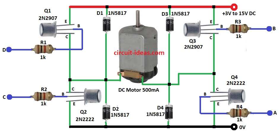
H-Bridge uses 4 transistors Q1, Q2, Q3, Q4 in shape like letter “H” around its motor.
Inputs A, B, C, D control transistors and chooses motor forward, reverse, stop or brake.
Forward: Q1 PNP ON, Q4 NPN ON and Q2, Q3 OFF.
Current flows from Vcc through Q1 and then through motor and then through Q4 to ground.
Reverse: Q3 PNP ON, Q2 NPN ON and Q1, Q4 OFF.
Current flows from Vcc through Q3 and then through motor and then through Q2 to ground.
Stop: All diagonal transistor pairs OFF with no current and motor stops.
Brake: Same side pair ON Q1 and Q3 or Q2 and Q4 and motor terminals are shorted to a quick stop.
Diodes D1 to D4 protect from back EMF.
Resistors R1 to R4 1k each limit base current and protect transistors and help smooth switching.
Formulas with Calculations:
Below are the formulas with calculations for Simple Transistor Based H-Bridge Motor Controller Circuit:
Base Resistor Calculations:
Base current:
I_B = I_C / h_FE
where,
- I_C is the motor current
- h_FE is the transistor gain.
Base resistor:
R_B = (V_in – V_BE) / I_B
V_BE = 0.7V for BJT.
Example:
I_C = 0.5A, h_FE = 100, V_in = 5V
I_B = 0.5 / 100 = 5mA
R_B = (5 – 0.7) / 0.005 = 860Ω is used for 1kΩ standard.
Motor Current Calculations:
I_motor = (V_supply – V_CE) / R_motor
V_CE = 0.2V.
Example:
V_supply = 12V, R_motor = 24Ω
I_motor = (12 – 0.2) / 24 = 0.49A (490mA).
Power in Transistor:
P = V_CE × I_C
Example:
V_CE = 0.2V, I_C = 0.49A
P = 0.2 × 0.49 = 0.098W this is much less than 2W rating then transistor will work safely.
How to Build:
To build a Transistor Based H-Bridge Motor Controller Circuit below mentioned steps are required to follow to design our own circuit:
- Gather all parts as from circuit diagram.
- Q1 base connects to signal D through R1.
- Q1 emitter connects to +3V to +15V DC.
- Q1 collector connects to Q2 collector.
- Q2 base connects to signal C through R2.
- Q2 emitter connects to GND.
- Q2 collector connects to Q1 collector.
- Q3 base connects to signal B through R3.
- Q3 emitter connects to +3V to +15V DC.
- Q3 collector connects to Q4 collector.
- Q4 base connects to signal A through R4.
- Q4 emitter connects to GND.
- Q4 collector connects to Q3 collector.
- Diodes D1 to D4 connects across emitter and collector of Q1 to Q4.
Conclusion:
Transistor Based H-Bridge Motor Controller Circuit with PNP + NPN transistors control DC motor forward and backward.
Circuit is cheap and easy to build.
It needs right transistors and resistors for good work.
The circuit is best for robots, automation and for small motors.