In this post we will give all easy information about Simple Water Softener Circuit
This one small device we can put on our water pipe which will help to make hard water to become soft.
Hard water make white stuff build up in pipe and machine and this make them not work good and cost money to fix.
This device send special signal like radio wave to change small rock inside hard water and then rock does not stick together which does not makes problem.
It work with small timer chip which keep small rock floating in water and does not stick on pipe.
But very important is some people say this thing not work so good and people still talk about it.
Better we talk to plumber or water expert and they tell will tell the best way to fix hard water in our home.
Circuit Working:
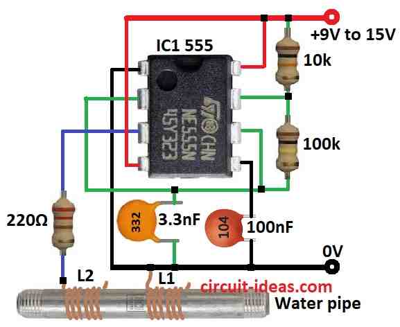
Parts List:
| Component Type | Description | Quantity |
|---|---|---|
| Resistors | 10k 1/4 watt | 1 |
| 100k 1/4 watt | 1 | |
| 220Ω 1/4 watt | 1 | |
| Capacitors | Ceramic 100nF | 1 |
| Ceramic 3.3nF | 1 | |
| Semiconductors | IC 555 | 1 |
| Water pipe (see the text) | 1 |
In this article we will talk about hard water.
Hard water have too much mineral like calcium which make problem sometimes.
But do not worry there is one cheap and easy DIY water softener which uses one common 555 IC chip.
This system is very low cost and even if it does not work we wont feel bad or lose much money.
This water softener work is an old idea from year 1930.
It says electric or magnetic field can make small calcium crystal join into big one and then it does not stick in pipe.
To make strong magnetic field we can put big magnet 2.5 gauss near water pipe or we can use electronic way.
We should check for one shop water filter which makes sound wave frequency around 15 kHz and 15 volts strong.
Important: If our pipe is metal then connect coil ends straight to the pipe and If pipe is plastic then connect coil ends with copper wire.
Coil size is not sure but we think L1 coil has 9 turns and L2 has 7 turns.
Still remember this is just an idea not 100% sure.
This softener uses one 555 IC to make square wave signal.
This signal connects to two wire coils and we have wrap coils around pipe where each coil has one end open.
Be sure coil do not touch anything and it must be safe and covered.
Also use separate power supply because in some places water pipe is grounded which can be dangerous.
Formulas:
One simple water softener circuit can use 555 IC chip.
We can set it to work in astable mode like a timer.
Astable Oscillator Mode:
In astable mode 555 chip make square wave signal again and again as it does not stop.
This signal helps to make magnetic field for soft water.
Frequency (f):
To find how fast it makes wave use this formula:
f = 1.44 / (R1 + 2 × R2) × C
where:
- R1 and R2 are resistor in ohms
- C is capacitor in farad
- f is frequency in hertz Hz
Duty Cycle (D):
This tells how much time signal stays ON vs OFF.
D = (R1 + R2) / (R1 + 2 × R2)
Duty cycle is percent (%) of ON time.
Pulse Width (T):
This tells how long each pulse is.
T = 1.1 × R × C
where:
- R is resistor ohms
- C is capacitor farad
- T is time in seconds
Note:
We can choose astable mode if we want continuous signal but it is good for basic water softener circuit.
This 555 IC is easy to use and cheap.
That is why many people like to use it for DIY projects like this.
How to Build:
To build a Simple Water Softener Circuit we need to follow the below mentioned connections steps:
555 Timer Setup:
- Set the 555 IC to astable mode to make square wave signal.
- Use resistors, capacitor and one potentiometer if needed to set signal speed frequency and ON/OFF time (duty cycle).
Making the Coils:
- Make two wire coils L1 with 9 turns and L2 with 7 turns.
- Keep the coils safe and be sure they do not touch pipe directly and they must have good insulation.
Circuit Connection:
- Join all parts like shown in the circuit diagram.
- Connect the output of 555 IC to both coils.
- If the pipe is metal then connect both coil ends to the pipe.
- If the pipe is plastic then use copper wire to connect both coil ends to pipe.
Power Supply:
- Use isolated power supply for safety and this will stop ground loop problems.
- Be sure power supply gives enough volts and current for this circuit to work well.
- After making the circuit test with water which we know is hard.
- Wait some time and see if water become softer.
Adjusting the Circuit:
- Use the potentiometer to change frequency or duty cycle if needed.
- Try small changes to make system work best.
Important Note:
- Be careful and work safe when using electric parts and water together.
Conclusion:
A Simple Water Softener Circuit is a small electronic device which uses electric or magnetic field to change the shape of minerals in hard water like calcium and magnesium.
When these ions change they do not stick so easily.
This helps stop buildup in pipes and machines and water becomes a little better.
Sometimes this circuit works good but not always it removes all hard stuff.
For very hard water it is better to use professional softener system that gives more strong and sure result.
Leave a Reply