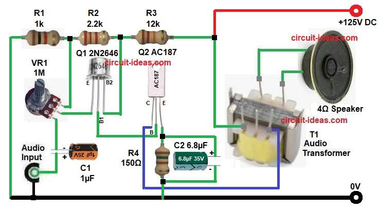
To begin with, the circuit in this article shows a simple high voltage mini audio amplifier which uses one UJT transistor Q1 2N2646 and one power transistor Q2 AC187.
This UJT Based High Voltage Mini Audio Amplifier Circuit works with a high supply of around +125V and it can drive a small 4 ohm speaker through a transformer.
The design stays simple with low component count and easy to build and also, it gives good amplification for small audio signals.
Circuit Working:
Parts List:
| Components | Values | Quantity |
|---|---|---|
| Resistors (All resistors are 1/4 watt) | 1k, 2.2k, 12k, 150Ω | 1 each |
| Potentiometer 1M | 1 | |
| Capacitors | Electrolytic 1µF 25V, 6.8µF 35V | 1 each |
| Semiconductors | Transistor 2N2646 UJT, AC187 Germanium | 1 each |
| Audio output transformer | 1 | |
| 4Ω Speaker | 1 | |
| Power Supply +125V DC | 1 |
First, the input audio signal enters through capacitor C1 and this capacitor blocks DC and allows only AC signal to pass and then, the signal goes to variable resistor VR1 and this resistor controls the input level.
Next, the signal reaches the UJT transistor Q1 and here, Q1 works as a signal modulator and trigger device as it shapes the waveform and controls the firing of the next stage.
After that, resistors R1, R2 and R3 form a biasing network and they set proper voltage levels for Q1 and Q2, because of this, the circuit stays stable.
Then, Q2 AC187 acts as the main amplifier transistor and it takes the small signal from Q1 and increases its power, the amplified signal flows through the primary winding of transformer T1.
Now, the transformer converts the high voltage, low current signal into low voltage and high current signal, which matches the 4 ohm speaker, so the speaker produces sound.
Finally, capacitor C2 works as a bypass capacitor which improves gain and reduces noise and resistor R4 controls emitter current of Q2 and keeps the transistor safe.
How to Build:
To build a UJT Based High Voltage Mini Audio Amplifier Circuit follow the below connection steps
- First, start the circuit by gathering all the parts as shown in diagram above.
- Next, take UJT transistor Q1 2N3436 and connect emitter pin to middle pin of VR1 output.
- Then take base1 pin and connect to base pin of transistor Q2.
- Then take base2 pin and connect between resistors R2 and R3.
- Next, take transistors Q2 AC187 and connect collector pin to transformer primary one end.
- Emitter pin connects to one end of resistor R4 and positive of C2 capacitor.
- Then base pin connects to base 1 of UJT transistor Q1.
- Next, take transformer T1 and connect primary end between +125V and Q2 collector.
- And secondary end connects to 4 ohm speaker.
- After that connect resistors R1, R2 and R3 in series from +125V positive supply and ground.
- Then VR1 upper pin goes between resistor R1 and R2, middle pin connects to emitter of UJT transistor Q1 and lower pin goes to negative end of capacitor C1.
- After that capacitor C1 connects between input and VR1.
- And capacitor C2 connects across R4 resistor.
- Lastly, speaker connects to transformer secondary ends.
Conclusion:
This UJT Based High Voltage Mini Audio Amplifier Circuit gives a simple and effective way to amplify audio signals which uses a UJT for signal control and power transistor AC187 for power amplification.
Here, the transformer helps match impedance and drives the speaker properly.
The circuit stays easy to build and works well for small audio projects and we can also modify values to adjust gain and performance.
Leave a Reply