Many small electronic circuits need continuous power supply but sometimes AC mains power fails, because of this our device stops working.
Therefore, we need a small Uninterruptible Power Supply.
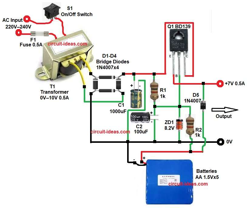
If we need 5V to 7V power supply with about 0.5A current then this 7V Backup Power Supply UPS Circuit is a good option as it does not use any IC, so it is simple to build.
This design uses a transformer, a bridge rectifier and an electrolytic capacitor and also it uses a Zener diode to control the output power transistor in the circuit.
The circuit gives about 7V constant output voltage and also we can use normal 1.5V AA batteries for the backup power
First, AC voltage converts to DC voltage, after that the circuit regulates the voltage, then the battery charges slowly and if power fails, the battery supplies power to the load and as a result, the device keeps working.
Circuit Working:
Parts List:
| Components | Values | Quantity |
|---|---|---|
| Resistors | 1k 1/4 watt | 2 |
| Capacitors | Electrolytic 1000uF 25V, 100uF 25V | 1 each |
| Semiconductors | Zener Diode 8.2V | 1 |
| Transistor BD139 | 1 | |
| Bridge Rectifier Diodes 1N4007 | 4 | |
| Protection Diode 1N4007 | 1 | |
| Step-down Transformer 0V–10V, 0.5A | 1 | |
| On/Off SPST Switch | 1 | |
| Fuse 0.5A | 1 | |
| Backup Batteries AA 1.5V × 5 | 1 Pack |
In the above circuit, AC mains power goes to transformer T1 and then T1 lowers the voltage to about 10V AC.
After that, AC voltage goes to the bridge rectifier using D1–D4 and these four diodes change AC to pulsating DC.
Next, capacitor C1 filters the DC voltage, so ripple becomes very small.
Then DC voltage goes to transistor Q1 and this transistor works like a series pass regulator.
Zener diode ZD1 gives reference voltage, so output voltage stays stable.
Resistor R1 gives base current to the transistor and at the same time, resistor R2 controls current for the Zener diode.
Capacitor C2 removes noise and it also helps keep the voltage stable.
During normal operation, the circuit gives about 7V output and at the same time, the battery charges slowly.
But when AC power fails the battery gives power to the load through diode D5 and so the load keeps running without interruption.
Formula with Calculation:
Formula for Output Voltage of Transistor Regulator:
Vout = Vz − Vbe
where,
- Vz is Zener voltage
- Vbe is base emitter voltage of transistor which is about 0.7V
Example for calculation:
Vz = 8.2V
Vbe = 0.7V
Vout = 8.2 − 0.7
Vout = 7.5V (approximately 7V output)
How to Build:
To build a 7V Backup Power Supply UPS Circuit follow the below connection steps:
- First, start the by collecting all the circuit parts as shown in circuit diagram.
- Then start with Transformer T1 with primary side one end connect to AC mains live through switch S1.
- And other other end of primary goes AC neutral through fuse F1.
- Then start with transformer T1 secondary side which go to bridge rectifier two input diodes end.
- Bridge rectifier one end go to filter capacitor C1 network and one goes to common GND.
- After that capacitor C1 positive connect to rectifier positive output and negative goes to ground.
- Transistor Q1 collector pin connect to DC input from C1 and R1.
- Base pin connect to junction of resistor R1, C1 positive, Zener diode anode and resistor R2.
- Emitter pin connects to output line of 7V output.
- Then Zener Diode cathode connect to transistor Q1 base and anode goes to ground.
- Resistor R1 one side goes to DC input and other side goes to junction of transitory base, C1 positive, Zener diode anode and resistor R2.
- Resistor R2 one side goes base of Q1 and other side goes to positive of 1.5V battery.
- Capacitor C2 positive side goes to base node and negative side goes to ground and battery negative.
- Battery negative goes to ground and positive goes to output through diode D5.
- Finally, diode D5 anode goes to battery positive and cathode goes to output line of 7V.
Conclusion:
This 7V Backup Power Supply UPS Circuit is a small and simple UPS project which provides about 7V regulated output.
During normal operation, the circuit powers the load and also charges the battery.
However, when AC power fails the battery automatically supplies power and therefore, the connected device continues to work.
The circuit is easy to build and also the components are cheap and easily available.
Because of this, it is useful for small electronics, routers, alarm systems and microcontroller circuits.
Leave a Reply