Electronic devices need controlled voltage to work safely and therefore, we use a regulated power supply.
However, AC mains voltage is not stable, so it is also not suitable for small electronic circuits, because of this we need to use voltage regulator circuits.
The 7805 regulator IC is a popular device which normally gives fixed 5V output, however, we can add extra components to adjust the output voltage, so the same IC can provide different voltage levels.
In this circuit, AC voltage is first converted into DC voltage and after that, the 7805 regulator controls the voltage level, as a result, the output voltage becomes stable and adjustable.
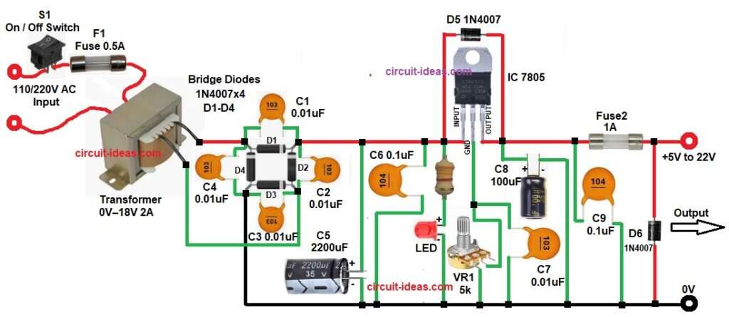
This 7805 Adjustable Power Supply Circuit can provide about 5V to 22V output with around 1A current depending on adjustment and therefore, it is simple and useful for a small lab power supply.
Circuit Working:
Parts List:
| Components | Values | Quantity |
|---|---|---|
| Resistors | 3.3k 1/4 watt | 1 |
| Potentiometer 5k | 1 | |
| Capacitors | Electrolytic 2200uF 35V, 100uF 35V | 1 each |
| Ceramic 0.01uF | 5 | |
| Ceramic 0.1uF | 2 | |
| Semiconductors | Voltage Regulator IC 7805 | 1 |
| Diode 1N4007 | 2 | |
| Bridge Rectifier Diodes 1N4007 | 4 | |
| Standard LED any color 5mm | 1 | |
| Fuse 1A, 0.5A | 2 | |
| SPST On / Off Switch | 1 | |
| Transformer secondary 0V–18V AC 2A, Primary 110V / 220V AC | 1 |
At first, AC mains enters the circuit a fuse and switch are connected for protection and control at the primary side of the transformer.
After that, the transformer reduces the high AC voltage to lower AC voltage for example, 230V AC becomes about 18V AC.
Next, the AC voltage goes to the bridge rectifier and this rectifier has four diodes therefore, these diodes convert AC voltage into pulsating DC.
After rectification, the filter capacitor smooths the DC voltage and as a result, ripple is reduced and the voltage becomes more stable.
Now, this DC voltage goes to the input pin of the 7805 regulator IC, normally the IC 7805 gives fixed 5V output, however, in this circuit a variable resistor is connected to the ground pin, because of this, the reference point shifts and therefore, the output voltage increases above 5V.
The variable resistor VR1 is used to adjust the output voltage, when VR1 changes, the ground reference also changes and consequently, the output voltage changes.
In addition, capacitors near the regulator improve stability and remove noise, also diode D5 protects the regulator from reverse voltage and similarly, another diode D6 at the output protects the circuit from reverse current.
Finally, a stable adjustable DC voltage appears at the output terminal.
How to Build:
To build a 7805 Adjustable Power Supply Circuit follow the below connection steps:
- Start the circuit first by assembling all the components as shown in the circuit diagram above.
- Then start with the transformer connection and connect the AC mains input to the primary side of the transformer.
- Also use a power switch and fuse in series with the AC line for safety.
- The secondary side of the transformer provides 0V – 18V AC output and then, these two secondary wires go to the bridge rectifier input.
- Next, use four 1N4007 diodes to make a bridge rectifier.
- After that connect the two transformer secondary wires to the AC inputs of the bridge rectifier.
- Then identify the positive and negative outputs of the bridge.
- The positive output goes to the filter capacitor and also to the 7805 input pin.
- The negative output becomes the main ground line of the circuit.
- Now take the 2200uF C5 electrolytic capacitor and connect the positive leg to the bridge rectifier positive output and connect the negative leg to the ground line.
- Next, start with IC 7805 connection and connect the input pin to the filtered DC voltage from the capacitor.
- However, the adjust (ground) pin will not go directly to ground, because of this circuit makes the voltage adjustable.
- The output pin goes to the output supply which provides about 5V to 22V.
- Then take the 5K potentiometer VR1 and connect one terminal of the potentiometer to ground.
- After that connect the middle terminal (wiper) to the adjust pin of the 7805 IC.
- Next, connect capacitor C7 with one end connects to VR1 and IC ground pin and the other end goes to the main ground supply of the circuit.
- Then connect capacitors C8 and C9 between output and ground in parallel.
- Also connect D5 1N4007 diode between output and input of the regulator.
- Next, connect another D6 1N4007 diode at the output line.
- After that connect C6 0.1uF capacitor between the input pin and ground of the 7805.
- Finally, take LED and R1 3.3k resistor and connect the resistor in series with the LED from the input line of the IC and then connect cathode of LED to GND.
Conclusion:
This 7805 Adjustable Power Supply Circuit is a simple and useful project to build which converts AC voltage into stable adjustable DC voltage.
The circuit uses easily available components and therefore, it is very suitable for beginners and electronics students.
Also, we can use this circuit as a small bench power supply and by adjusting the potentiometer, we can get different output voltages easily.
Finally, the 7805 adjustable regulator circuit has simple design and reliable operation therefore, many electronic projects use this circuit.
Leave a Reply