In this post, the below designed circuit gives a stable 5V DC output with high current up to 4A which uses the 7805 voltage regulator IC and multiple TIP41C transistors connected in parallel, because the normal 7805 IC alone gives around 1A current and we add external power transistors to increase the output current.
Moreover, this 5V 4A Power Supply Circuit using IC 7805 and Parallel Transistors is useful for Arduino power supply, USB charging projects, digital circuits, small amplifier boards and embedded systems.
Also, the design uses simple components, so it becomes easy to build and test.
Circuit Working:
Parts List:
| Components | Values | Quantity |
|---|---|---|
| Resistors | 0.22Ω 5W | 4 |
| 470Ω 1/4W, 3.3Ω 1/4W | 1 each | |
| Semiconductors | Power transistor NPN TIP41C | 4 |
| Driver transistor PNP BC557 | 1 | |
| Voltage Regulator IC 7805 | 1 | |
| Power Supply Input 12V DC minimum 5A | 1 | |
| Output 5V DC upto 4A | 1 | |
| Heat Sink for TIP41C and IC 7805 | As required |
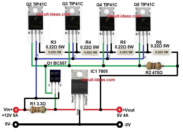
In the above diagram, the 12V DC input enters the circuit through the input terminal and goes to the 7805 IC, then the IC regulates the voltage and keeps the output fixed at 5V.
Next, the Q1 BC557 transistor works as the driver transistor which gives the required base current to the four TIP41C transistors.
After that, the four TIP41C transistors are connected in parallel and this increases the output current capacity up to 4A, also each transistor shares part of the load current, so the circuit can safely give more current than the 7805 alone.
In addition, one 0.22Ω 5W resistor is connected to the emitter of each TIP41C transistor, therefore a total of 4 emitter resistors are used.
These resistors help in equal current sharing between all four transistors, if one transistor takes more current, the voltage drop across its resistor increases and as a result, that transistor reduces its conduction slightly then the other transistors share the remaining current.
Because of this the emitter resistors improve stability and also they reduce overheating and protect the transistors from current imbalance.
Finally, the combined output from all four emitter resistors gives a stable 5V DC output with up to 4A current.
How to Build:
To build a 5V 4A Power Supply Circuit using IC 7805 and Parallel Transistors follow the below connection steps:
- Start, by collecting all the components as shown in the circuit diagram above.
- Next, take IC1 7805 and connect its input pin to the 12V supply line.
- Then connect the IC ground pin to the common ground line.
- After that, connect the IC output pin to the 5V output line and the transistor control line.
- Next, take Q1 BC557 transistor and connect its emitter pin to the input side line.
- Then connect the base pin of Q1 through resistor R1 to the input pin line of IC1.
- After that, connect the collector pin of Q1 to the base drive line of TIP41C transistors Q2 to Q5.
- Next, take Q2-Q5 TIP41C transistors and join all the base pins together to the control line from Q1 and the resistor network.
- Then connect all the collector pins of TIP41C transistors to the 12V input line.
- After that, connect resistors R3 to R6 to the emitter pin of each transistor from Q2 to Q5.
- Next, join the other ends of all four 0.22Ω resistors together and connect them to the 5V output line.
- Then take resistor R1 and connect it between the input line and the base control path.
- After that, take resistor R2 and connect it in the transistor base bias line as shown in the circuit.
Conclusion:
To conclude, this 5V 4A power supply circuit gives a stable and reliable 5V DC output from a 12V input source.
The parallel TIP41 transistors increase the output current up to 4A and also at the same time, the IC 7805 keeps the output voltage regulated at 5V and because the circuit uses simple and easily available components it is a good choice for power supply projects.
However, always use proper heat sinks because the circuit produces high power loss during operation.
Finally, this is a simple, practical and effective 5V high current regulator circuit for many electronics applications.
Leave a Reply