Over the past 56 years, operational amplifiers have changed electronics design in a big way and before that time, designers built amplifiers with many separate transistors and extra components and later, companies released op amp ICs that made amplifier circuits smaller, cheaper and easier to build.
Furthermore, this project uses the popular LM324 operational amplifier IC; the circuit takes a very small sound signal from an electret microphone and increases the signal strength and after amplification, the speaker or earbud can hear the sound clearly.
Moreover, the circuit works from a simple 9V power supply and also, the design uses only a few low-cost components, because of this, beginners can build the circuit easily for learning and testing audio amplification concepts.
Circuit Working:
Parts List:
| Components | Values | Quantity |
|---|---|---|
| Resistors (All resistors are 1/4 watt) | 5k, 1k | 1 each |
| 100k | 2 | |
| Potentiometer 10k | 1 | |
| Capaciator | Ceramic 0.1uF | 1 |
| Semiconductors | IC LM324 | 1 |
| Electret Mic | 1 | |
| 8Ω Speaker | 1 | |
| Dual Power Supply ±9V DC | 1 |
To begin with, this amplifier circuit uses one section of the LM324 quad op amp IC, the microphone captures sound waves and converts them into tiny electrical signals, but however, the signal remains very weak and therefore, the op amp increases the signal voltage and sends it to the speaker.
The circuit also includes a variable resistor for volume adjustment, in addition, feedback resistors control the gain of the amplifier.
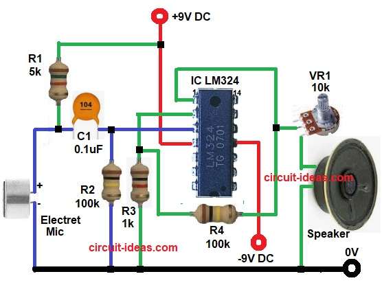
Here, the above circuit begin with, the electret microphone which needs power for operation, therefore, resistor R1 provides bias voltage from the 9V supply to the microphone.
So when sound reaches the microphone, the microphone creates a small AC audio signal; capacitor C1 blocks DC voltage and allows only the audio signal to pass into the LM324 op amp input.
Next, resistor R2 provides input biasing for the non-inverting terminal of the op amp, the LM324 IC then amplifies the incoming audio signal.
Also, resistors R3 and R4 form the feedback network and this network controls the voltage gain of the amplifier circuit, the amplified output appears at the output pin of the LM324 IC.
After that, variable resistor VR1 adjusts the output volume level and finally, the speaker converts the amplified electrical signal back into sound.
How to Build:
To build a Op-Amp Based Video Amplifier Circuit follow the below connection steps:
- First, gather all the circuit parts as in diagram above.
- Next, connect pin 4 of LM324 to +9V supply and connect pin 11 to ground.
- After that, connect microphone negative terminal to ground and connect microphone positive terminal to resistor R1 and capacitor C1
- Then connect the other side of resistor R1 to +9V power supply,
- Now connect capacitor C1 output to pin 3 of LM324.
- Next, connect resistor R2 between pin 3 and ground and connect resistor R3 between pin 2 and ground.
- After that, connect resistor R4 between pin 1 and pin 2.
- Lastly, take output from pin 1 and connect VR1 between output and speaker and connect speaker negative terminal to ground.
Testing the Circuit:
- First, check all wire connection properly.
- Then connect 9V battery supply to circuit.
- Now speak close to microphone and slowly turn VR1 for sound adjustment.
- After that speaker gives amplified sound output clearly.
Conclusion:
To conclude, this Simple LM324 Microphone Amplifier Circuit provides a simple and low-cost way to amplify weak audio signals.
The project helps beginners understand operational amplifier basics, feedback networks and audio signal amplification.
Also, the circuit uses very few components so construction becomes easy on breadboard or PCB.
With proper assembly and testing the amplifier produces clear sound output through earbuds or small speakers.
Leave a Reply