This Simple 220V Diac Controlled LED Flasher Circuit is an easy way to make LED blink using AC power;
Moreover, the circuit is simple and we can make it with one or more flashing LEDs by using high-voltage DC from the mains.
Also, we can use it as mains power indicator or just for flashing light effect.
Circuit Working:
Parts List:
| Components | Quantity |
|---|---|
| Resistors | |
| 22k 1/4 watt | 2 |
| 220Ω 1/4 watt | 2 |
| Capacitor | |
| Electrolytic 10µF 100V | 1 |
| Semiconductors | |
| Diode 1N4007 | 1 |
| Diac DB3 | 1 |
| LED 5mm 20mA | 1 |
This circuit use diac to switch LED ON and OFF again and again; diac mostly used in circuits to make pulse and trigger things like SCR and triac.
When voltage is low diac stay open with only tiny current pass, but when voltage go high up to breakdown level diac start to conduct more current.
Usually it need around 35V DC to start working.
Also different from SCR diac can work both sides means in both directions.
Furthermore, this circuit uses a DB3 diac, which is easy to find.
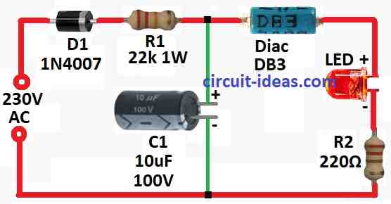
Diode D1 converts AC into high-voltage DC, while resistor R1 limits the current to protect the diac and LED, because the LED mostly stays OFF.
Also, when the capacitor fully charges, the voltage becomes high enough, so the diac turns ON and the LED lights up.
Resistor R2 ensures LED does not get too much current and keep it safe around 30mA and after LED flash a capacitor C1 start to discharge and voltage goes down by stopping the diac and LED turn OFF.
Hence, this charging and discharging again and again make the flashing.
Therefore, how fast it flash depend on size of capacitor C1, big value means slower flash and small value means faster.
Lastly, if voltage does not reach diac level with current R1 one can try 10k resistor but ensure it is 5 watt type.
Formula:
Below are some formulas we can use when checking how 220V Diac LED flasher circuit works.
This formula tell how long capacitor C1 take to charge and discharge, as it controls how fast LED blink.
Formula is:
τ = R × C
where:
- τ (tau) is time in seconds
- R is resistance R1 in ohms
- C is capacitor C1 in farads
Because all parts not always exact but real flash time can change a bit from what one calculates.
Few more things to remember:
Capacitor C1 should have voltage rating more than peak AC line voltage and when C1 voltage reach breakdown point diac DB3 act like a switch and let current go to LED.
Resistor R2 keep LED safe by limiting how much current which goes through it.
Be careful this circuit uses high voltage which can prove to be very dangerous and if not sure how to work with mains power better call licensed electrician to stay safe.
How to Build?
To build a Simple 220V Diac Controlled LED Flasher Circuit below mentioned are the assembling steps:
Safety First:
- First, only try this if one knows how to work with high voltage and never touch anything while the circuit connects to mains power.
Component Placement:
- Next, put all parts on proper board or inside project box and then follow the circuit diagram to place parts in correct way.
Wiring:
- Connect one wire from AC mains to one side of diode D1 and connect other side of D1 to one side of resistor R1.
- Then connect other side of R1 to one side of diac and other side of diac connects to longer leg anode of LED.
- Also, shorter leg cathode of LED connects to one side of resistor R2 and other side of R2 connects to one side of capacitor C1.
- Finally, the other side of C1 connects back to other wire of AC mains.
Testing and Adjustment:
- Check all wires and parts carefully, then connect them correctly and place the circuit inside a shockproof box.
- Connect to AC mains and watch if LED starts blinking and if flash rate is not good change value of R1 as said before.
Safety Measures:
- Always use a shockproof box and do not open wires or parts, it should be visible when using mains power.
Note:
- This circuit connect straight to high voltage AC without using isolation.
- So be very careful by keeping the circuit inside closed box and do not ever touch when plugged in.
Conclusion:
Overall, this Simple 220V Diac Controlled LED Flasher Circuit which uses easy to find parts to make LED blink using AC mains power.
Also, if we build it carefully and follow all safety steps it can work as mains power indicator or just flashing light for fun or for other use.

Leave a Reply