Make ones fish bowl bright and colorful by this Aquarium LED Lighting Circuit which work like tiny sun for fish tank; also it have special LED lights that light up water.
Some circuit are also smart enough, as they can turn ON or OFF by self when room get bright or dark like day and night time.
Also, some circuit can change color to make fish tank look more nice and pretty.
Circuit Working:
Parts List:
| Components | Values | Quantity |
|---|---|---|
| Resistors (All resistors are 1/4 watt ) | R1 10M | 1 |
| R2 1M | 1 | |
| R3 220Ω | 1 | |
| R4 220Ω | 1 | |
| R5 220Ω | 1 | |
| R6 220Ω | 1 | |
| R7 220Ω | 1 | |
| R8 220Ω | 1 | |
| Variable Resistor VR1 100k preset | 1 | |
| Capacitor | C1 Ceramic 0.22µF | 1 |
| Semiconductors | IC 4060 | 1 |
| Transistors BC547 T1, T2, T3 | 3 | |
| Light Dependent Resistor (LDR) | 1 | |
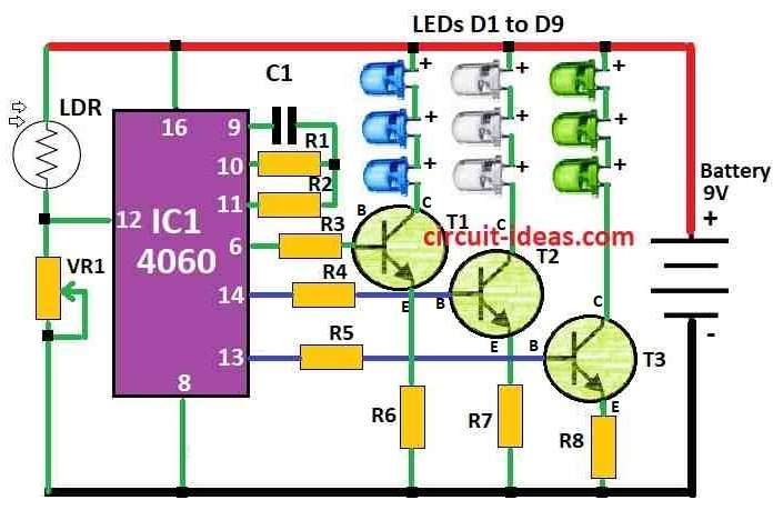
| LEDs D1 to D9 Blue, white, and green 5mm, 20mA | 9 | |
| Battery 9V | 1 |
This bright aquarium light circuit makes fish tank look like nature, here the LED lights turn ON by self at sunset; also they change color with white, blue, green and make aquarium look very nice.
During morning time lights turn OFF by self and this light uses LDR sensor to know when it is dark or bright.
When at day time LDR gets low resistance and so IC1 stay OFF and when night comes LDR get high resistance and make pin 12 of IC1 goes low and IC1 start working.
CD 4060 is counting chip with ten outputs, which make outputs high one by one depending on parts C1, R1, R2.
Also, the LEDs connect to transistors T1, T2 and T3 because these transistors help turn the LEDs ON and when the circuit starts, it waits for 5 minutes, and then Q6 turns ON while the blue LEDs shine for 5 minutes.
After that Q7 become high and green LEDs shine for next 10 minutes and blue and green LEDs stay ON together for 10 minutes and then make nice mix color.
Then Q9 turn ON after 20 minutes and white LEDs turn ON and stay for 20 minutes.
In this time we can see many color mix with blue-white, green-white, blue-green-white which makes aquarium look very beautiful.
Tip: Keep LDR where it can see sunlight in day and dark in night.
Formula:
This LED light circuit for a fish tank uses a formula to find the flashing speed; first, we should decide how fast we want the LED to blink, and this speed is called fLED.
Here, is simple formula to find oscillator frequency (fosc) for IC 4060:
fosc = 1 / (2.3 × R × C)
where:
- C is capacitor between pin 9 and ground
- R is resistor on pin 10
Important Tips:
Choose correct R and C values to get right LED flashing speed and before final setup test everything on breadboard and change the parts if needed.
Maybe we need to adjust the parts more based on our own circuit.
How to Build:
To build a Aquarium LED Lighting Circuit follow the below mentioned steps:
- First, put CD 4060 IC on breadboard or PCB.
- After that, connect VDD pin to power positive (+) and VSS pin to power negative (–).
- Then one side of LDR connects to power (+) other side connects to ground (–) through a resistor.
- Join point between LDR and resistor to connect pin 12 of CD 4060.
- Next, put capacitor C1 from pin 9 clock input to ground.
- Connect resistors R1 and R2 in series between pin 9 and power (+) and also join between R1 and R2 goes to pin 10 of Q4 of CD 4060.
- Now connect white, blue and green LED strings to collector side of transistors T1, T2, T3.
- Connect the emitters of all transistors to ground and connect the base of each transistor to the IC outputs.
- Connect T1 base to Q6, T2 base to Q7 and T3 base to Q8 of CD 4060.
- Connect power supply to positive of VDD and negative to VSS
- Put LDR in place where it get light in day and dark at night.
- Turn ON power and see LED working, LEDs should turn ON when dark and should change color with white, blue, green; also in morning lights should turn OFF.
Adjustments:
- If LED timing is not perfect then change values of R1, R2, C1 until it works how one wants.
Note:
- Check all wires and parts carefully and make sure they connect correctly and if anyone is not sure how to do this, ask someone who knows electronics or soldering better.
Conclusion:
Overall, Aquarium LED Lighting Circuit is special circuit that use LED lights to light up fish tank; it can turn ON or OFF by itself depending on room light like day or night.
Also, it can show different colors to make aquarium look nice and pretty and also keep fish happy and healthy.
Leave a Reply