This 30V 1Amp Transformerless Power Supply Circuit works like small adapter for our electronic, as it takes normal high voltage electric and change it to low safe voltage to what our devices need.
No large transformer is required because the circuit uses special components such as capacitors and diodes to perform the same function.
Like if we have 30V 1A power supply with no transformer then it may take high voltage and give out 30 volt steady with max 1 amp which is good for small electronic use.
Also, this kind of power supply is good for small project, when we want cheap and easy way to change electric for our gadget.
But this power supply also have some problem which are not so safe because there is no isolation between input and output, so its little risky.
Circuit Working:
Parts List:
| Components | Values | Quantity |
|---|---|---|
| Resistors | 330k 1/4 watt | 1 |
| 5Ω 2W | 1 | |
| 100k 1/4 watt | 2 | |
| Capacitors | PPC 470nF 400V | 1 |
| PPC 560nF 700V | 1 | |
| Electrolytic 1µF 50V | 1 | |
| Electrolytic 2200µF 35V | 1 | |
| Electrolytic 22µF 400V | 1 | |
| Semiconductors | Thyristor SCR 5P4M | 1 |
| Fast diode BY127 | 1 | |
| Diode BA100 | 2 | |
| Zener 15V 1W | 2 |
To begin with, this circuit is for transformerless power supply which is good for medium current use.
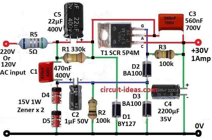
During the negative half-cycle, capacitor C5 charges to the peak voltage from the power line and when the positive half-wave arrives, the thyristor turns ON and then, the circuit transfers charge from C5 to C4.
Current start flow through thyristor when voltage on C4 goes below level set by Zener diode D4 and D5 and because of this the output voltage stays stable even if input voltage or load changes.
Control signal for thyristor work like this: main AC voltage goes through capacitor C1 to Zener diodes D4 and D5 which cut it to 30 Vpp.
Hence, thyristor turns ON at start of this limited voltage which passes through C2 and R2.
How to Build:
To build a 30V 1Amp Transformerless Power Supply Circuit follow the below mentioned connections steps:
Gather Parts:
- First, assemble all the required parts needed for the circuit like capacitors, resistors, thyristor and Zener diode.
Make Circuit:
- After that, use circuit diagram from above diagram and build it on breadboard or PCB.
Capacitor Setup:
- Then put capacitor C1 in series with AC voltage source and after that, put capacitor C2 in parallel with C1 and in series with resistor R1.
Thyristor Setup:
- Now connect gate of thyristor from where C2 and R2 meet and connect anode of thyristor to positive side of C5 and cathode to output side.
Zener Diode Setup:
- Put Zener diode D4 and D5 in parallel with C2 and R1.
Final Check:
- Also, check all the wire and part connections again and be sure no wires are short or with wrong connection.
- Turn ON the power and see if circuit works correct and also be careful as this is high voltage so one should follow safety.
- Check output voltage with different load and check the voltage stays stable.
Note:
- Finally, be careful while working with high voltage also we should only try if one is aware of what they are doing and take safety measures at all time.
Conclusion:
Overall, this 30V 1Amp Transformerless Power Supply Circuit is small size and with low cost, as it is good for low power electronics.
But it is not having isolation between input and output so we must be careful and always use safety when using this type of power supply.

Leave a Reply