Normal car battery has liquid inside and Gel Cell Battery Charger Circuit uses jelly but not liquid.
Jelly make battery strong and work in any position and to charge gel battery we need special charger, as this charger gives right power but not too much.
Too much power can hurt battery and special charger keep battery safe and good.
Circuit Working:
Parts List:
| Components | Values | Quantity |
|---|---|---|
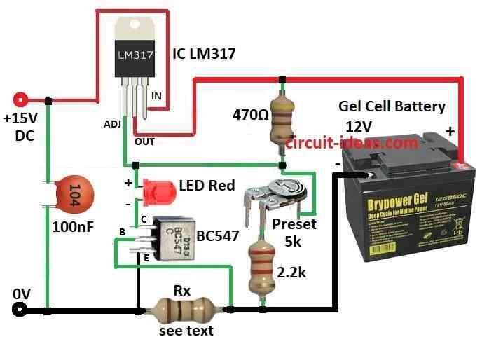
| Resistors (All resistors are 1/4 watt unless specified) | 470Ω, 2.2k | 1 each |
| Rx = 0.7/max current | 1 | |
| Preset 5k | 1 | |
| Capacitor | Ceramic 100nF | 1 |
| Semiconductors | IC LM317 | 1 |
| Transistor BC547 | 1 | |
| LED Red 5mm 20mA | 1 | |
| 12V Gel cell battery | 1 |
This circuit charges gel battery with 300mA, 650mA or 1.3A, as it depends on resistor in 0V line and to set 13.4V output, adjust 5k preset.
When battery reaches 13.4V current goes down to very low and if we want 650mA or 1.3A then we need better plug pack.
Red LED means charging; as battery voltage goes up the current goes down and LED turns OFF when current drop about 5%.
After that current slowly goes to almost zero.
Formulas:
We can use this formula to find output voltage Vout for LM317 circuit:
Vout = 1.25V × (1 + R2 / R1)
where:
- Vout is the voltage we want
- 1.25V is the fixed inside LM317
- R2 a 2.2 kΩ preset resistor connects the adjust pin to the output.
- R1 is the resistor from adjust to ground for 470 ohms in circuit diagram
Note:
Adjust pin (Iadj) has very small current of 50 microamps so most time we ignore it and that is why formula does not use it.
Use resistors with 1% tolerance for better result.
More things:
Lowest voltage LM317 can give is around 1.25V and max voltage depends on input voltage and dropout 2 to 3V less than input
Therefore, we need more steps to show the values of R1 and R2.
How to Build:
To build a Gel Cell Battery Charger Circuit follow the below mentioned steps for connections:
Design the Circuit:
- First, choose right parts like in diagram.
Power Supply Section:
- Then give +15V DC to input pin of LM317.
- Next, connect output pin of LM317 to 12V gel battery through 470 ohm resistor.
- After that, connect adjust pin to red LED and BC547 transistor.
Voltage Regulator Section:
- Also, use LM317 to control voltage and use resistors preset to set correct output voltage.
Current Limiting Section:
- Now put current sensing resistor in 0V line and add transistors and resistors to control current.
LED Indicator:
- Use LED to show charging with LED ON means charging and LED OFF means full charge.
Test the Circuit:
- Before battery test with dummy load and if working fine then connect real gel battery.
Monitor Charging:
- Check the voltage and current during charging and stop the charger when the battery becomes fully charged.
Safety Tips:
- Be careful and avoid short circuit and overheating and follow battery manufacturer instructions.
- Also, if not sure ask help from electronics expert.
Conclusion:
To conclude, this Gel Cell Battery Charger Circuit charges gel batteries safely; it includes a transformer, a rectifier, a voltage control stage, and a current limiter.
In addition, it keeps battery safe and works well.
Leave a Reply