Modern electronics need good power control especially for high current and low voltage use.
MIC29302WT is strong LDO regulator and it gives high current with small voltage drop, it is good for battery devices, car electronics and microcontroller power.
Also, it gives up to 3A current, so it can handle heavy circuits.
Output voltage is from 1.24V to 28V which is very flexible and dropout voltage is low to 0.5V so less heat and better efficiency.
Furthermore, it has built-in safety with overcurrent and heat protection and works well even in tough conditions, so it is good for stable and reliable systems.
This post for Designing a High Current, Low Voltage Regulator Circuit with the MIC29302WT shows how it works and where to use it which is best for high current and low voltage tasks.
Understanding LDO helps make systems better and efficient for new or old designs, so here in this tutorial we make a simple, low cost, easy circuit with common parts.
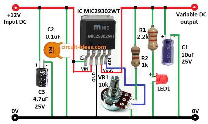
Circuit Working:
Parts list:
| Components | Values | Quantity |
|---|---|---|
| Resistor | 2.2k 1/4 watt | 1 |
| 1k 1/4 watt | 1 | |
| Potentiometer 10k | 1 | |
| Capacitor | Electrolytic 10μF/25V | 1 |
| Electrolytic 4.7μF/25V | 1 | |
| Ceramic 0.1μF | 1 | |
| Semiconductors | IC MIC29302WT | 1 |
| LED any 5mm 20mA | 1 |
In this circuit capacitors C2 and C3 connect 12V unregulated DC to MIC29302 input pin and input and output DC share same ground.
Then EN pin connects to input positive and stays high to turn ON the regulator.
Also, resistors R2 and VR1 make voltage divider for ADJ pin and then VR1 potentiometer changes output voltage.
LED on output line shows if Vout is present and capacitor C1 filters the output DC, therefore this is a DC voltage regulator with adjustable output.
Moreover, microchip also makes fixed output versions of this IC and inside LDO has 3 main parts: reference voltage, error amp and pass element.
It uses feedback system and compares output with reference and if output changes then it adjusts inside parts to fix voltage.
Formulas and Calculations:
To get best result with MIC29302WT pick right parts and connect them well.
Output Voltage Formula:
To set output voltage Vout:
Vout = Vref × (1 + R1 / R2)
where,
- Vref is about 1.235V for this IC.
Example:
R1 = 2.2kΩ, R2 = 1kΩ
Vout = 1.235 × (1 + 2200 / 1000) = 1.235 × 3.2 = 3.95V
PD = (Vin − Vout) × Iout
Use this to check heat and add heatsink if needed.
Thermal Resistance:
To keep IC safe from overheating:
Rth = (Tj,max − Ta) / PD
Tj,max = 125°C (IC limit)
where,
- Ta is the room temperature
- PD is a power from above
Notes:
Check capacitor and LED polarity and ensure we connect all wires and components tightly.
Hence, turn VR1 slowly to set correct voltage and then watch if circuit is stable and working fine; hence, this gives strong, low voltage, high current output if built properly.
How to Build:
To designing a High Current, Low Voltage Regulator Circuit with the MIC29302WT follow the below mentioned connections steps:
- First, take all parts shown in the circuit diagram above.
- Next, connect pin 1 EN to pin 2 (Vin) of MIC29302WT.
- After that, connect pin 3 GND to 0V of power supply.
- Then connect pin 4 Vout to variable DC output.
- Now connect pin 5 Adj to middle leg of VR1 10k, first leg of VR1 goes to output line through R2 1k and then third leg of VR1 goes to GND.
- Further, put C2 0.1µF and C3 4.7µF between +12V input and GND and then connect R1 2.2k and LED in series from output to GND.
- Finally, place C1 10µF from output to GND.
Conclusion:
To conclude, Designing a High Current, Low Voltage Regulator Circuit with the MIC29302WT makes simple and strong DC voltage regulator, as it gives stable output, even for high current.
Also, using feedback and voltage divider VR1 and resistors we can change output voltage.
In addition, the circuit is good for many uses like testing, projects or real products and its easy design, works well and is quite reliable.
Leave a Reply