A Automatic Light Sensor Buzzer Circuit using Transistors is a simple electronic project which gives alarm sound when light level changes.
In this circuit, an LDR (Light Dependent Resistor) senses the surrounding light, and when the room becomes dark, the resistance of LDR increases and because of this, transistor stages switch ON one by one and finally the buzzer starts with a sound.
This circuit is useful for dark room alarm system, automatic night warning device, cupboard light alarm and small security applications.
Also, the circuit uses easily available components, so beginners can make it easily without much difficulty.
Circuit Working:
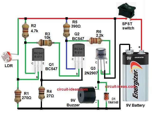
Parts List:
| Components | Values | Quantity |
|---|---|---|
| Resistors | 270Ω, 4.7k, 10k, 27Ω, 390Ω, 2.2k | 1 each |
| LDR standard | 1 | |
| Semiconductors | Transistor BC547 | 2 |
| Transistor 2N2907 | 1 | |
| 9V Buzzer | 1 | |
| Diode 1N4148 | 1 | |
| SPST Switch | 1 | |
| 9V Battery | 1 |
At first, the LDR senses the light intensity, in bright light the LDR resistance becomes low and because of this, current flows through the LDR path and keeps transistor Q1 in OFF state or very low conduction state.
Next, because Q1 remains OFF the transistor Q2 does not get enough base current through resistor R3, so Q2 also stays OFF.
After that, transistor Q3 also remains OFF because Q2 does not give drive current through resistor R6 and finally, the buzzer remains silent.
Now when darkness comes, the LDR resistance increases suddenly, because of this, less current flows through the LDR and the voltage at base of Q1 changes and then Q1 turns ON.
After that, Q1 gives drive current to Q2 through resistor R3, so Q2 also turns ON.
Next, Q2 sends current to the base of Q3 through resistor R6 and as a result, Q3 switches ON and completes the buzzer circuit path.
Therefore, the buzzer starts producing sound and also, diode D1 protects the circuit from reverse voltage spikes and unwanted transient current.
How to Build:
To build a Automatic Light Sensor Buzzer Circuit using Transistors following steps need to follow for connections:
- First, gather all the circuit parts as in diagram above.
- Then start, with Q1 BC547 transistor emitter pin connected to ground line through R4 resistor.
- Base pin connected to junction of LDR and R1.
- Collector pin connected to resistor R2 and resistor R3 junction
- Next, start with second transistor Q2 BC547 base pin connected through R3 from Q1 collector.
- Collector pin connected to R5 and R6 resistor network.
- Emitter pin connected to emitter pin of transistor Q1
- Next, with third transistor Q3 2N2907 base pin connected through R6 from Q2 collector.
- Collector pin connected to positive pin of 9V buzzer.
- Emitter pin connected to positive supply of of the circuit.
- Then take, LDR one terminal goes to positive line and second terminal goes to Q1 base junction and R1
- Then take, buzzer with positive side connect to Q3 collector and diode D1 cathode and negative side of buzzer goes to ground line.
- Next, Diode D1 cathode connects to buzzer positive side and collector of transistor Q3 and anode goes to ground.
- Finally, battery positive goes to switch S1 to positive supply rail and negative goes to main ground rail.
Conclusion:
This Automatic Light Sensor Buzzer Circuit using Transistors is a simple and useful transistor project which senses darkness with the LDR and quickly turns ON the buzzer through three transistor stages.
Moreover, the circuit has low cost, is easy to build and works well for beginners and small security applications.
Also, because of its simple design and reliable working, it is a great circuit for school, hobby and practical electronics projects
Leave a Reply