Input signal with some frequency goes into FVC (frequency to voltage converter) and output is DC voltage which matches that frequency.
Furthermore, we can make Frequency to Voltage Converter Circuit using IC 555 in monostable mode and FVC is useful for many things where we need to check frequency like:
- Check speed RPM of spinning machine with motor, etc.
- Check liquid flow by watching how turbine spins
- Use light sensor like photodetector that give pulses to measure light
- Watch vibrations to see if machine have problem
Circuit Working:
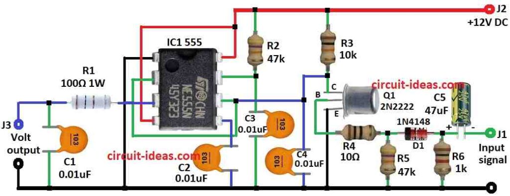
Parts List:
| Components | Values | Quantity |
|---|---|---|
| Resistors (All resistors are 1/4 watt unless specified) | 100Ω 1W | 1 |
| 10k | 1 | |
| 10Ω | 1 | |
| 1k | 1 | |
| 47k | 2 | |
| Capacitors | Ceramic 0.01μF | 4 |
| Electrolytic 47μF 25V | 1 | |
| Semiconductors | IC 555 | 1 |
| Transistor 2N2222 | 1 | |
| Diode 1N4148 | 1 |
555 IC in monostable mode is main part of this circuit, in monostable mode 555 give one output pulse when it get trigger signal and how long pulse stays depends on input signals frequency.
Making Input Signal Ready:
Input signal which is square or sine wave goes through diode D1 and capacitor C5 and then this makes sharp spike and this sharp spike ensures 555 trigger every time; also the best spike voltage is around 2/3 to 1/3 of VCC.
Choosing Pulse Length:
Resistor R3 and capacitor C4 control the pulse time, therefore, designers refer to them as timing components; in addition, we can change the values of R3 and C4 to adjust the pulse time according to our requirements.
Cleaning Output Signal:
555 output may have noise, so add resistor R1 and capacitor C1 to filter it and this gives clean output voltage.
Transistors Job:
Transistor Q1 helps the circuit, it connects to timing capacitor C4 and when sharp spike comes transistor turns ON and discharges C4; then it turns OFF and C4 charges again and this happens in sync with input signal.
Modification of the Circuit:
We can change R3, C4, R1 or C1 to adjust the circuit for our needs like different frequency or output voltage.
Summary:
This circuit smartly uses 555 IC to change input frequency into matching DC voltage output.
Formulas:
This circuit changes frequency into voltage using 555 IC in monostable mode and output voltage goes up when input frequency goes up.
How Monostable Mode Works:
When signal comes to pin 2 trigger, pin 3 output goes high for short time and time of this high pulse depends on R1 and C1.
Timing Formula:
T = 1.1 × R1 × C1
where:
- T is pulse time in seconds
- R1 is resistor in ohms Ω
- C1 is capacitor in farads F
Convert Frequency to Voltage:
Output voltage is like:
Vout = 1 / T = 1 / (1.1 × R1 × C1)
So:
High frequency with short T means high voltage and low frequency with long T means low voltage
Final Tip:
Therefore, change R1 and C1 values to fit our signal and what we need from the circuit.
How to Build:
To build a Frequency to Voltage Converter Circuit using IC 555 follow the below mentioned steps for connections:
- First, connect pin 1 of 555 IC to ground.
- Next, connect pin 2 to pin 6 of 555 IC.
- After that, connect pin 3 to voltage output through resistor R1 and then put capacitor C1 between R1 and ground.
- Now connect pin 4 and pin 8 of IC to +12V DC supply.
- Connect pin 5 to ground through capacitor C2 and also connect capacitor C4 to pin 6 and then to ground.
- Then connect pin 7 to +12V through resistor R2.
Transistor Q1 Wiring:
- Now collector of Q1 connects +12V through resistor R3, base of Q1 connects input signal through resistor R4, diode D1 and capacitor C5 and also emitter of Q1 connects to ground
- After that, put resistor R5 between ground and point between R4 and D and then put resistor R6 between ground and point between D1 and C5
Safety Tips:
Follow safety rules to avoid shock or damage and be careful with power supply and always double check the connections.
Conclusion:
Overall, this Frequency to Voltage Converter Circuit using IC 555 in monostable mode is to convert signal frequency into matching DC voltage.
Also, this circuit offers a low-cost and useful solution; however, always build and operate the circuit safely.
Leave a Reply