In this post we will talk about a 12V Regulated Power Supply Circuit which gives steady 12V output using few parts.
Hence, this circuit is good for small projects which need clean power and easy to build and use.
What is 12V Regulated Power Supply Circuit:
Firstly, this project is an electric circuit that changes moving input voltage into steady 12V output.
Moreover, this circuit powers many electronic parts that need 12V DC all the time.
In addition, even if the input voltage or load changes, the output still remains stable at 12V because of proper voltage regulation.
Circuit Working:
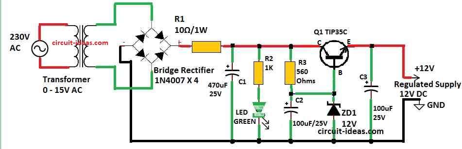
Parts List:
| Components | Quantity |
|---|---|
| Resistors | |
| 10Ω 1W | 1 |
| 1k 0.5W | 1 |
| 560Ω 0.5W | 1 |
| Capacitors | |
| Electrolytic 470µF 16V | 1 |
| Electrolytic 100µF 16V | 2 |
| Semiconductors | |
| Bridge Rectifier 1N4007 | 4 |
| Zener Diode 12V 1W | 1 |
| LED Green 3.3V 20mA | 1 |
| Transistor TIP35C | 1 |
| Transformer 0-15V | 1 |
Firstly, Zener diode is main part in this circuit it work in reverse side which is in Zener breakdown.
Also, transistor Q1 work like changeable resistor and it change its resistance when base current change and Zener diode gives fixed voltage to control this.
Output voltage (Vout) we get using this formula:
Vout = Vz − VBE
where:
- Vout is output voltage
- Vz is Zener voltage
- VBE is voltage between base and emitter of transistor
Moreover, formula help to know how voltage changes in circuit with transistor and how VBE drop affect output voltage.
In addition, this is very important when we design circuits where we need an exact and stable voltage.
Advantages and Disadvantages:
Advantages:
- This circuit is easy and cheap way to control voltage.
- Also, output voltage stay always stable and it is good for projects that need more current.
Disadvantages:
- This circuits are only good for low or medium power use and they are not as efficient as other ways to control voltage.
How to Build:
Follow the below mentioned construction steps for building a 12V Regulated Power Supply Circuit:
- First, a step-down transformer is used to get an AC input of at least 15V.
- After that, use bridge rectifier or 4 diodes 1N4007 in bridge shape to change AC to DC.
- Then, put capacitor C1 to filter and smooth the DC voltage.
- Next, add LED to show power is ON.
- After that, connect resistor R3 and capacitor C2 in series from plus to minus side to give VBC to transistor Q1.
- Furthermore, put 12V Zener diode ZD1 in reverse way to base of transistor Q1.
- Also, when Zener breaks down it controls base of transistor and gives fixed output voltage.
- Then, if we change Zener diode value we can get different output voltage for different needs.
Components Functions:
- Additionally, Zener Diode ZD1 gives fixed voltage (Vz) to circuit as it works in Zener breakdown mode and its important part is to keep voltage stable.
Transistor Q1 – TIP35C
- First, the TIP35C is an NPN BJT transistor designed for amplifier and for switch applications, it handles high current with low heat loss.
- Also, it is good for medium power projects and comes in TO220 plastic case which is easy to cool and handle.
Conclusion:
Finally, 12V Regulated Power Supply Circuit is cheap and good way to get steady voltage in electronics.
As a result, if person understand basic idea and how to build it they can change circuit for different voltage it needs.
However, need to choose right Zener diode and transistor to give wanted voltage and handle enough current.
Also, we can use this circuit in many projects, but it has efficiency and power limitations for high load applications
Leave a Reply