LPG Gas Leakage Detector Circuit using Arduino is important safety tool which can stop accidents, as this project uses Arduino to check LPG gas in air.
Also, if gas level goes too high then buzzer make sound and LCD show warning, hence, through this circuit people know danger fast.
Arduino Code:
#include <LiquidCrystal.h>

// Define pins
const int gasSensorPin = A0;
const int buzzerPin = 13;
const int threshold = 300; // Adjust threshold as needed

// Initialize LCD
LiquidCrystal lcd(12, 11, 5, 4, 3, 2);

void setup() {
  // Set up sensor and LCD
  pinMode(gasSensorPin, INPUT);
  pinMode(buzzerPin, OUTPUT);
  lcd.begin(16, 2);
}

void loop() {
  int sensorValue = analogRead(gasSensorPin);

  // Check for gas leak
  if (sensorValue < threshold) {
    lcd.clear();
    lcd.setCursor(0, 0);
    lcd.print("No Gas Leak");
    digitalWrite(buzzerPin, LOW);
  } else {
    lcd.clear();
    lcd.setCursor(0, 0);
    lcd.print("Gas Leak Detected!");
    digitalWrite(buzzerPin, HIGH);
  }

  delay(100);
}
Code Explanation:
- Code include Liquid Crystal library for LCD.
- Gas sensor pin connects to Arduino analog pin to read gas level.
- Buzzer pin connects to Arduino digital pin to control buzzer.
- We use a set threshold value to detect gas leaks and we can adjust this value to increase or decrease sensitivity.
- In the setup() function, we start the LCD and configure the sensor and buzzer pins.
- In loop() Arduino keeps reading sensor, check with threshold and then turns buzzer and LCD ON or OFF as needed.
Circuit Working:
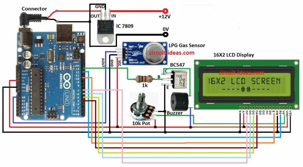
Parts List:
| Components | Quantity |
|---|---|
| Resistors | |
| 1k 1/4 watt | 1 |
| Potentiometer 10k | 1 |
| Semiconductors | |
| Arduino Uno board | 1 |
| LPG gas sensor module (MQ-2 or similar) | 1 |
| 16×2 LCD display | 1 |
| Buzzer | 1 |
| IC 7809 | 1 |
| Transistor BC547 | 1 |
In this project we have used Arduino board, gas sensor MQ-2, buzzer and LCD screen, also Arduino reads gas sensor and shows message on LCD and turns ON the buzzer if needed.
Also, we can change sensor sensitivity, here, MQ-2 sensor checks LPG gas by change in resistance, as more gas means less resistance.
Then the sensor generates an analog voltage and the Arduino reads it, next, it compares the value with a threshold, and if the value exceeds the threshold, the system detects a gas leak.
After that, Arduino turns ON the buzzer using transistor and shows warning on LCD, through this system keeps checking gas level and gives updates until its safe again.
How to Build:
To build a LPG Gas Leakage Detector Circuit using Arduino we need to follow the below mentioned steps:
- First, collect all parts shown in the circuit diagram.
- Next, connect IC1 7809 to give stable 9V DC power to Arduino.
- Then connect 10k pot 1st pin connects to VCC of LCD, 2nd pin connects to VO of LCD and then 3rd pin connects to GND of LCD.
We describe the connection of the LCD to the Arduino below.
- Now connect LCD VCC pin to 5V on Arduino, connect LCD GND pin to GND on Arduino and then connect LCD Anode pin to 5V through pot resistor to control brightness.
- Then RS pin goes to Arduino pin 12, e Enable pin goes to Arduino pin 10.
- After that, D4, D5, D6, D7 pins goes to Arduino pins 4, 5, 6, 7 and then RW pin connects to GND on Arduino.
We have describe the connections for the buzzer, BC547 transistor and LPG gas sensor below.
Buzzer and BC547 Transistor Connection:
- One leg of buzzer goes to collector of BC547, other leg of buzzer goes to 5V on Arduino.
- BC547 base connects to Arduino pin 13 through 1k resistor and emitter of BC547 connects to GND.
LPG Gas Sensor Connections:
- VCC pin connects to 5V on Arduino, GND pin to connects GND on Arduino and then AOUT pin connects to analog pin A0 on Arduino.
Note:
- Always follow safety rules when working with gas and for better results use high sensitivity gas sensor.
- Use a relay for big loads like fans or alarms and if required add battery backup for nonstop working.
- Add wireless feature for alerts and remote watch.
Conclusion:
Overall, the LPG Gas Leakage Detector Circuit using Arduino acts as a life-saving safety device, additionally, we can build a strong system using Arduino and basic components; however, we must test and adjust the system properly.
Leave a Reply