This circuit shows about FET overload current protection using transistor and MOSFET.
If the load draws too much current or the output gets short-circuited then this Overcurrent Protection Circuit using Transistor and FET can help you.
The main purpose of this circuit is to protect load from high current, like when current increases above limit then circuit quickly turns OFF the MOSFET and stops damage.
This design is simple, low cost and useful for power supplies, battery circuits and small electronic systems.
Circuit Working:
Parts List:
| Components | Values | Quantity |
|---|---|---|
| Resistors | 1k, 220k 1/4 watts, 1Ω 2W | 1 each |
| Potentiometer 100k | 1 | |
| Capacitor | Ceramic 0.01µF | 1 |
| Semiconductors | NPN Transistor BC547 | 1 |
| N-channel MOSFET IRFZ44N | 1 | |
| Diode 1N5402 | 1 | |
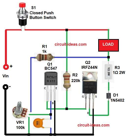
| Closed Push Button Switch | 1 |
Input voltage Vin come into circuit first and then switch S1 control ON and OFF.
MOSFET Q2 work like main switch for load and when circuit start then Q2 allow current pass and load work normal.
Resistor R3 sense current because it connect in series with load.
If current is small, then voltage across R3 stays very low and transistor Q1 does not turn ON, so MOSFET Q2 keeps working.
As the load takes more current, voltage across R3 increases and this voltage goes through diode D1 and resistor path to Q1.
After the voltage becomes high enough then Q1 starts working and reduces the gate voltage of MOSFET Q2, so Q2 stops conducting.
Because of this current stop going to load and circuit protect load from overload.
Capacitor C1 give small delay and stop false trigger and variable resistor VR1 help to adjust current limit level.
Formulas with Calculations:
Current limit formula:
I = 0.7 / R3
where,
- I is the current limit in ampere
- 0.7 is the transistor turn ON voltage base-emitter voltage of Q1
- 1 is the value of resistor R3 in ohms
Now add value as above:
I = 0.7 / 1
So,
I = 0.7A (700mA)
When current reaches about 0.7 amp then circuit will trip, after that MOSFET will turn OFF and load will be protected.
Note: This formula gives approximate current limit of 0.7A which is suitable for small and medium loads in project use.
How to Build:
To build a Overcurrent Protection Circuit using Transistor and FET follow the below connection steps:
- Start, by assembling all the components as in circuit diagram.
- Then connect positive supply Vin to one side of switch S1 and connect other side of switch S1 to main circuit positive line
- MOSFET Q2 connect drain pin of Q2 goes to load negative side, connect source of Q2 to ground and connect gate of Q2 to control point junction of R1 and Q1 collector.
- Load connection connect one side of load to positive supply and connect other side of load goes to resistor R1 and R3
- Current sensing resistor R3 connect in series with load and diode anode.
- Then start with other transistor Q1 emitter pin connect to ground, collector pin connect to junction of R2 and MOSFET gate and base pin connect to VR1 middle pin and capacitor C1.
- Resistor R1 connect one end to load and other end to VR1.
- Resistor R2 one end connect to positive supply and other end connect between MOSFET gate node and transistor Q1 collector pin.
- Variable resistor VR1 one side connect to resistor R1 one end, middle pin goes to gate of Q2 MOSFET, third leg goes to gnd.
- Diode D1 connect anode to one end of resistor R3 and cathode goes to drain pin of MOSFET Q2.
- Capacitor C1 one end connect between base of Q1 middle pin of VR1 and other end of C1 goes to GND.
Conclusion:
This Overcurrent Protection Circuit using Transistor and FET gives simple and effective overload protection.
It uses few components and works fast, where we can adjust current limit easily using variable resistor.
This circuit protect sensitive devices and power supply from damage and it is good for beginners and small projects.
Leave a Reply