This project for Rain Detector Circuit using Arduino shows how to detect rain.
Rain sensor plate feels water drops.
Module gives analog and digital signal.
Arduino reads signal.
LED glows when rain starts.
This is low cost and easy project for beginners.
Arduino Coding:
int rainAnalog = A0;     // analog signal from sensor
int rainDigital = 7;     // digital rain signal
int redLed = 13;         // red LED for rain alert
int greenLed = 9;        // green LED for no rain
int buzzer = 8;          // buzzer pin

void setup() {
  pinMode(rainDigital, INPUT);
  pinMode(redLed, OUTPUT);
  pinMode(greenLed, OUTPUT);
  pinMode(buzzer, OUTPUT);
  Serial.begin(9600);
}

void loop() {

  int analogValue = analogRead(rainAnalog);
  int rain = digitalRead(rainDigital);

  Serial.print("Analog Value: ");
  Serial.println(analogValue);

  if (rain == 0) {
    digitalWrite(redLed, HIGH);
    digitalWrite(greenLed, LOW);
    digitalWrite(buzzer, HIGH);
  }
  else {
    digitalWrite(redLed, LOW);
    digitalWrite(greenLed, HIGH);
    digitalWrite(buzzer, LOW);
  }

  delay(300);
}
Code Explanation:
- A0 reads rain level.
- D7 gives wet or dry signal.
- Rain detected then red LED and buzzer is ON, green LED is OFF.
- No rain then green LED is ON, red LED and buzzer is OFF.
- Serial monitor shows analog value.
- Serial monitor shows water strength by analog value.
- Higher analog means more water.
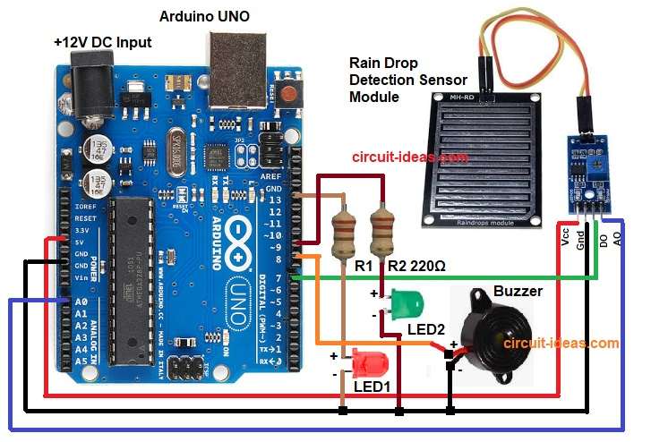
Circuit Working:
Parts List:
| Component | Quantity |
|---|---|
| Resistor 220Ω 1/4 watt | 2 |
| Arduino UNO | 1 |
| Rain Drop Detection Sensor Module | 1 |
| LED Red and Green | 1 each |
| Buzzer 5V | 1 |
| USB Cable | 1 |
Rain plate has two metal lines.
Water makes conduction between lines.
Resistance decreases when water present.
Sensor module converts resistance change to voltage.
Arduino reads voltage from analog pin.
Arduino also reads digital output from DO pin.
Buzzer gives sound when rain is detected.
If rain is detected then Red LED1 turns on to show rain is present.
If no rain then Green LED2 turns on to show no rain.
Formulas with Calculations:
Sensor acts like a variable resistor.
With water, resistance goes low and AO voltage goes high.
Circuit uses voltage divider formula:
Vout = Vin * (R2 / (R1 + R2))
here,
- Vout is voltage across R2.
- Vin is input voltage.
- R1 is fixed resistor inside the sensor module.
- R2 is sensor resistance inside the module.
Example assume:
- Dry sensor is about 100k ohm.
- Wet sensor is about 20k ohm.
- Vin is 5V.
Dry sensor example:
R2 = 100k ohm
Vout = 5 * (100k / (50k + 100k))
Vout = 5 * (100k / 150k)
Vout = 5 * 0.666
Vout = 3.33V
Wet sensor example:
R2 = 20k ohm
Vout = 5 * (20k / (50k + 20k))
Vout = 5 * (20k / 70k)
Vout = 5 * 0.285
Vout = 1.42V
Arduino reads these voltages as numbers from 0 to 1023.
How to Build:
To build a Rain Detector Circuit using Arduino following are the steps one should follow:
- Take all the parts as shown in circuit diagram.
- Connect rain sensor plate to module: + to +, – to -, S to SIG.
- Module VCC pin connect to Arduino 5V.
- Module GND pin connect to Arduino GND.
- Module AO pin goes to Arduino A0.
- Module DO pin goes to Arduino D7.
- LED1 red positive leg go to Arduino D13 through 220 ohm resistor.
- LED1 negative leg go to GND.
- LED2 green positive leg through 220 ohm resistor to Arduino D9
- And LED2 green negative leg go to GND
- Buzzer positive pin go to Arduino D8
- Buzzer negative pin go to GND
- Breadboard is used to hold LED and resistor.
Conclusion:
This is simple and easy Rain Detector Circuit using Arduino.
Rain sensor plate gives water level.
Arduino shows rain condition with LED.
Useful for automatic windows, weather station, farms and home systems.
Easy to build and with low cost.
Leave a Reply