24V Flasher Circuit can ON-OFF 24V thing like lightbulb again and again and we can use to turn signal or warning flash light also.
Furthermore, this circuit uses IC 555 which is common for making timer or flasher and we can also change flash speed by adding resistor and capacitor to IC 555.
Hence, this way is not so flexible but easy, as we can make simple 24V flasher by using with easily available parts.
Circuit Working:
Parts List:
| Components | Values | Quantity |
|---|---|---|
| Resistors | 1k 1/4 watt | 2 |
| 470k 1/4 watt | 1 | |
| Capacitors | Ceramic 0.1μF | 1 |
| Electrolytic 10μF 50V | 1 | |
| Semiconductors | IC 555 | 1 |
| IC 7812 | 1 | |
| Transistor 2N2222 | 1 | |
| Diode 1N4007 | 1 | |
| 12V Relay | 1 | |
| 24V Bulbs | 2 |
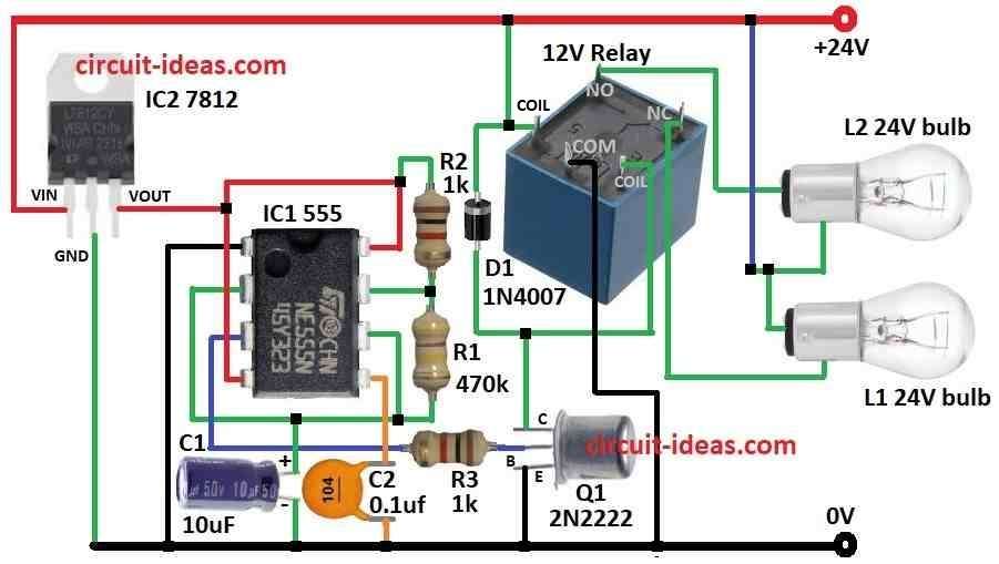
To begin with, the relay controls two bulbs in the flasher circuit, here we connect the positive terminals of both bulbs to the 24V supply, while we connect their negative terminals to the relay for ON/OFF control.
Relay have 3 main pins:
- COM (Common) always connected to relay.
- NO (Normally Open) not connected at first but connected when relay is ON.
- NC (Normally Closed) connected at first and then disconnected when relay is ON.
Hence, because of this only one bulb lights at a time.
555 IC for Timing:
Relay must turn ON/OFF again and again to make flash.
The IC 555 generates timing signals; we use the IC 555 in astable mode, where it produces continuous pulses with ON time (Ton) and OFF time (Toff).
Bulb Control with Timing:
The 555 output controls the bulbs; bulb 1 turns ON during Ton, while bulb 2 turns ON during Toff, so we show this process in the simulation.
Powering the Circuit:
Circuit runs on 24V but relay and IC 555 need lower voltage and IC 7812 voltage regulator changes 24V to 5V for IC 555 and relay.
Boosting 555 Output with Transistor:
Sometimes the IC 555 output from pin 3 does not provide enough strength to drive a relay, therefore, we use a 2N2222 NPN transistor to increase the power.”
Moreover, 555 sends signal to transistor base through resistor and transistor acts like switch and gives enough current to turn relay ON/OFF.
Formulas:
Flash rate how fast the bulbs blink depends on 2 parts in 555 IC astable mode: resistor R1 which connects pin 1 and pin 8 of 555 IC and capacitor C1 which connects pin 2 and pin 6 of 555 IC.
Flash rate formula is:
F = 1.44 / (R1 × C1)
where:
- F is the flash rate in Hz
- R1 is the resistor value in ohms Ω
- C1 is the capacitor value in farads F
Therefore, change R1 or C1 to control flash speed, higher R1 or C1 then slower will be the flash. and lower R1 or C1 then faster will be the flash.
How to Build:
To build a 24V Flasher Circuit we need to follow the below mentioned steps for connections:
- First, pin 1 of IC1 555 connects to ground
- Next, pin 2 connect to pin 6 also connect C1 capacitor from pin 2 and pin 6 to ground
- After that, pin 3 connects to base of Q1 transistor through R3 resistor
- Now pin 4 & pin 8 connects to Vout of IC2 7812.
- Then pin 5 connects to ground through C2 capacitor
- Also, R1 connects between pin 6 and pin 7 and R2 connects from pin 7 to positive supply Vout
Power Supply IC2 7812 Regulator:
- Now Vin pin of IC2 connects to +24V, GND pin of IC2 connects to 0V ground and then Vout pin connects to positive rail for IC1 555
Transistor and Relay Connection:
- Also, Q1 collector to COM pin go to 12V relay, Q1 base connects from pin 3 of IC1 555 through R3 and then Q1 emitter connects to ground
Relay coil:
- One pin connects to +24V, other pin connects to collector of Q1
- Relay COM pin connects to ground, relay NO pin connects to L2 bulb 2 and relay NC pin connects to L1 bulb 1; then d1 diode connects across relay coil pins with reverse polarity for protection
Safety Notes:
- Be careful with 24V can shock so use proper voltage source
- Double check the wiring and keep safety first always when working with circuits
Conclusion:
To conclude, in this 24V Flasher Circuit IC 555 controls bulb flash speed, as the transistor and relay handle bigger current and IC 7812 gives safe voltage to IC 555
Finally, while building this circuit be careful and should stay safe!
Leave a Reply