LEDs (light-emitting diodes) are used in many applications because they are durable, efficient and versatile also they are used in decoration and signaling and adjusting LED brightness is important in such applications.
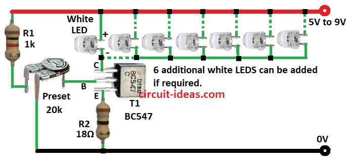
This Simple Adjustable Brightness Control Circuit for LEDs uses BC547 NPN transistor, resistors, one preset (variable resistor) and a white LED to change brightness.
Hence, with this circuit user can easily control LED brightness.
Circuit Working:
Note:
One white LED takes 20mA current, 7 LEDs use 20mA × 7 = 140mA total.
Transistor T1 must handle this 140mA and total current should not go over T1s limit.
Parts List:
| Components | Values | Quantity |
|---|---|---|
| Resistors | 1k 1/4 watt | 1 |
| 18Ω 1/4 watt | 1 | |
| Preset 20k | 1 | |
| Semiconductors | Transistor BC547 | 1 |
| LED white 5mm 20 mA | 1 |
Voltage on the preset resistor controls the BC547 transistor and then this transistor works like a switch in the LED brightness control circuit.
The circuit works with 5V to 9V DC power and a small current to the base of BC547 lets big current flow from collector to emitter.
Also, this small base current helps control bigger current to the LED.
After that, the 20k preset changes base current and changing resistance changes LED current and brightness.
Then the 18Ω resistor keeps LED safe by limiting its current and the 1k resistor protects the transistor by limiting base current.
Formulas:
Here are simple formulas for adjustable LED brightness circuit:
V = I × R
where,
- V is the Voltage
- I is the current
- R is the resistance
Transistor Current Gain:
IC = β × IB
where,
- IC is the collector current
- IB is the base current
- β is the gain (hFE) of transistor
LED Current Formula:
ILED = (Vsupply − VLED) / Rtotal
where,
- VLED is the voltage drop of white LED
- Rtotal 18Ω + RLED resistor in series with LED
- Vsupply is the power supply voltage
Therefore, this helps to find how much current flows through LED.
How to Build:
To build a Simple Adjustable Brightness Control Circuit for LEDs following steps need to follow for connections:
- First, collect all parts as shown in the circuit diagram.
- Next, connect BC547 transistor collector to positive supply through white LED.
- After that connect base of BC547 to middle leg of preset VR1.
- Now connect emitter of BC547 to GND through resistor R2.
- Then from positive to GND connect resistor R1 and preset VR1 in series and then connect VR1 upper leg to positive middle leg to transistor base and last leg to GND.
Conclusion:
Overall, this Simple Adjustable Brightness Control Circuit for LEDs controls circuit by using one preset and BC547 NPN transistor.
Additionally, it offers simple white LED brightness control and works perfectly for decoration, indicator lights and mood lighting.
Hence, by changing preset user can set different brightness levels which is good for school projects, hobby work or small home designs.
Leave a Reply