This small and Electronic Gatekeeper Circuit work like little guard for our door, it uses sensor to check if someone comes or goes from gate.
Sensor can be like light beam or something we can step on and if person goes through without permission then circuit make alarm or send message to tell us.
So we can keep place safe and know when people come or go.
Circuit Working:
Parts List:
| Components | Values | Quantity |
|---|---|---|
| Resistors (All resistors are 1/4 watt) | 10k | 2 |
| 1k | 2 | |
| 100Ω 1W | 1 | |
| Preset 10k | 1 | |
| Capacitors | Electrolytic 100µF 25V | 1 |
| Electrolytic 470µF 25V | 1 | |
| Semiconductors | IC LM741 | 1 |
| Transistor BC547 | 1 | |
| Phototransistor L14F1 | 1 | |
| Diode 1N4007 | 1 | |
| LED Red 5mm 20mA | 1 | |
| IR LEDs 5mm | 3 | |
| Relay 12V | 1 |
This circuit work like gatekeeper and tell us when someone passes through the gate.
Here, the alarm can be AC bell or lamp and it can turn ON for 1 minute and then stop if light beam comes back.
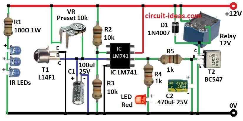
Also, it uses infrared IR rays like light barrier when someone break this beam and system turn ON the alarm using phototransistor.
Furthermore, the phototransistor used here is L14F1 is a high gain NPN Darlington type and when it sees IR rays it conduct and its collector connects to ground.
Moreover, one IC work like simple voltage comparator and resistors R2 and R3 make voltage divider and give half power supply 6V to inverting input of IC.
Then non-inverting input of IC connect to collector of phototransistor.
Normally IC output stay low because T1 is conducting, but when someone break the IR beam then T1 collector goes high and this make non-inverting input voltage higher than inverting input and so IC output goes high.
This high output turn ON the T2 which drives the relay.
Capacitor C1 give small delay to non-inverting input to stop false alarm and capacitor C2 keep T2 ON for short time even if IR beam come back.
Hence, it very important to align IR beam correct with phototransistor and if not then alarm stays ON.
Normal range of circuit is 2 meters but if we put lens in front of IR LED then it goes up to 5 meters and if we do not want AC alarm then use buzzer instead of relay.
We can also use laser pointer instead of IR LED and this make range up to 25 meters but be careful and do not look at laser directly and also put phototransistor inside small case with small hole in front this will stop light from outside getting in.
Finally, fix IR LED on one gate pillar and phototransistor on other side and be sure they line up perfect.
Formula:
This formula help to find gain G of inverting amplifier using LM741 IC:
G = −Rf / Rin
here,
Note:
For more full details how to use and try the sample circuits check with LM741 datasheet; different companies maybe have small change in specification so always see latest datasheet for correct information
How to Build:
To build a Electronic Gatekeeper Circuit you need to follow the below mentioned assembling steps:-
- First, connect collector of phototransistor to inverting input of IC, connect emitter to ground and then connect base of T1 to cathode side of IR LED.
- Next, put resistors R2 and R3 between positive power and ground to make voltage divider.
- Then connect non-inverting input of IC to middle point of R2 and R3.
- Now connect inverting input of IC to collector of phototransistor.
- After that, connect relay to IC output through transistor T2.
- Connect C1 between collector of phototransistor and inverting input of IC and connect C2 between base of T2 and ground.
- Be sure IR LED and phototransistor face each other correctly as this create light beam like barrier.
- Now turn power ON and break the IR beam using hand or object, alarm should turn ON when beam breaks and stops when beam come back.
- Also, if circuit is not working good then try change sensitivity of phototransistor or change delay time using capacitor.
Important Note:
- So be careful when working with electronic parts and some parts and voltage can be dangerous so be sure one should know what they are doing and always follow safety rules.
Conclusion:
To conclude, an Electronic Gatekeeper Circuit is security system which help to watch and control who go in or out from one place like gate or entrance, also it uses sensor to see if someone move or come in.
Furthermore, if someone comes without permission then it make alarm or send message to alert people, hence this type of circuit gives more safety because it watches in real time and help to protect the buildings or property.
Leave a Reply