The Fire Alarm Circuit using Thermistor and IC 555 help to find and warn people about fire, as this design uses IC 555 and thermistor to check temperature change and maybe fire.
Furthermore, thermistor is special part which feels the temperature change, also circuit is easy to make and thermistor changes resistance with heat and if hot then resistance goes low and if cold then resistance goes high and this help to know if fire happens.
Circuit Working:
Parts List:
| Components | Quantity |
|---|---|
| Resistors (All resistors are 1/4 watt) | |
| 470Ω | 4 |
| 560Ω | 1 |
| 33k | 1 |
| 47k | 1 |
| 2.2k | 1 |
| Capacitors | |
| Ceramic 0.01μF | 1 |
| Ceramic 0.04μF | 1 |
| Electrolytic 10μF 25V | 1 |
| Semiconductors | |
| IC 555 | 1 |
| Thermistor | 1 |
| Transistor BC547 | 1 |
| Transistor BC557 | 1 |
| Transistor 2N2222 | 1 |
| Diode 1N4001 | 1 |
| LED Red 5mm 20mA | 1 |
| 8Ω Speaker | 1 |
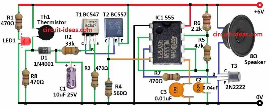
In this circuit IC1 555 timer work like sound oscillator and IC1 get power from transistors T1 and T2.
Then IC1s pin 3 connect to transistor T3 2N2222 base and T3 make speaker give alarm sound.
After that, capacitor C2 and resistors R5, R6 control how fast IC1 oscillate and when thermistor Th1 gets hot its resistance goes low and then positive voltage goes through R2 and diode D1 to transistor T1 base.
Now capacitor C1 charges and keep alarm sound longer, as bigger C1 means longer sound time.
Next, T2 applies a positive voltage to pin 4 (reset pin) of IC1 when it conducts and R4 keeps IC1 OFF when the reset pin does not receive a positive voltage.
If Th1 cools down then resistance goes high and and diode D1 stops C1 from losing charge.
Then thermistor should be on heat proof material like mica to avoid damage and it also stops T1 from turning ON when not needed.
Also, LED turns ON to show power is ON and we can use 6V supply or 6V battery to run this circuit.
Formulas:
Using this circuit we can make this simple fire alarm with IC 555 and thermistor and we can also decide how it works and which parts to use; so to build this we should use basic formula:
IC 555 in Monostable Mode:
To find output time T we can use this formula:
T = 1.1 × R × C
Choose values for resistor R5, R6 and capacitor C2 to set alarm time.
Example:
If R5 = 47k, R6 = 2.2k and C2 = 0.04μF then we should use formula to get time T.
Note:
This alarm uses basic design principles and formulas; the values of resistors, capacitors and transistors depend on the required sensitivity and operating conditions.
Therefore, we may need to adjust some component values based on testing and the environment in which the circuit operates.
How to Build:
To build a Fire Alarm Circuit using Thermistor and IC 555 we need to follow the below mentioned assembling steps:
- First, put all parts together like circuit design shows.
- Next, pin 1 of IC 555 goes to ground.
- Then pin 2 connect to pin 6 of IC 555.
- Now, pin 3 connect to base of transistor T3 using resistor R7.
- After that, pin 4 connect between collector of T2 and resistor R4.
- Also, pin 5 connect to ground through capacitor C3.
- Then pin 7 connect to pin 6 through resistor R5 and capacitor C2 goes to ground.
- Now resistor R6 goes from pin 7 to +6V supply and also pin 8 connect to +6V power.
- Lastly, resistor R1 and LED1 goes in series between +6V supply and ground.
T1 Transistor Connections:
- Now collector of T1 connect to base of T2, base of T1 goes to ground through resistor R2 and capacitor C1 and then emitter of T1 goes to ground.
T2 Transistor Connections:
- Now collector goes to ground through resistor R4, base connect to collector of T1 and then emitter goes to +6V supply.
- Also, diode D1 connects through resistor R2 and resistor R8 to ground and then thermistor (Th1) goes between D1 and +6V supply.
T3 Transistor for speaker Connection:
- Collector goes to one side of 8 ohm speaker and other side of speaker to +6V, base of T3 connect to pin 3 of IC 555 and then emitter goes to ground.
Conclusion:
Overall, this Fire Alarm Circuit using Thermistor and IC 555 is cheap and works well and when temperature goes high then thermistor change resistance and circuit turns ON alarm sound.
Finally, it is easy to make useful and good for places where early fire warning is important.
Leave a Reply