Do anyone want to try make its own small radio station?, then this post can help.
This post show how to build a easy and FM Transmitter Circuit (100 meters range) which works between 87.5 to 108 MHz on FM radio.
Transmitter uses simple circuit with special transistor and antenna to send our signal.
This one is different from other small transmitter where there is no need of turning knob, as it uses special part to change frequency little bit.
That make it more easy to tune radio and hear what we have send.
WARNING: Radio law is not same in every country, it can be illegal to use this without license, so we should please be careful.
What is a FM Transmitter Circuit:
FM transmitter is small electronic thing it uses frequency modulation to make and send radio signals.
In FM the signal changes the frequency of main carrier signal and by depending how loud input sound is.
But in AM amplitude modulation it does not change the frequency it can change how strong amplitude the signal is.
Circuit Working:

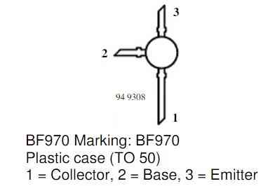
BF970 Pinout Diagram:
Parts List:
| Component | Description | Quantity |
|---|---|---|
| Resistors | All resistors are 1/4 W CFR | |
| 100k | 1 | |
| 22k | 1 | |
| 1k | 1 | |
| 6.8k | 2 | |
| Preset 100k | 1 | |
| Capacitors | ||
| Ceramic 1μF | 1 | |
| Ceramic 10nF | 1 | |
| Ceramic 1nF | 1 | |
| Ceramic 6.8pF | 1 | |
| Ceramic 22pF | 1 | |
| Ceramic 100nF | 2 | |
| Semiconductors | ||
| Transistor BF970 | 1 | |
| Varicap Diode BB105 | 1 |
Transistor work like oscillator and makes radio signal all the time.
Frequency is set by LC circuit and it uses coil L1 and varicap diode and this varicap diode help to change frequency and this makes FM signal.
When we change DC voltage going to varicap with trimmer P1 then the diode change its capacitance and then frequency of signal also changes.
First to tune it, we can change the coil L1 and add or remove turns to get close to right frequency.
Then we can use trimmer P1 to fine-tune and this will help get better sound and signal.
We can connect music source like cassette or MP3 player to input.
This sound signal changes the frequency a bit so audio can connect through radio waves.
Antenna is simple and is just 7 cm copper wire with cover which connects to oscillator and send out signal in air.
Circuit is simple but it can send signal up to 100 meters, as it works using 5V USB or 5 to 12V power supply or even battery.
How to Build:
Following are the steps to make a FM Transmitter Circuit (100 meters range):
- On breadboard put the small RF transistor of PNP type, silicon planar.
- Connect transistor legs emitter, base and collector to right place on breadboard.
- Now as shown in circuit diagram add trimmer P1 and varicap diode BB105 to the setup.
- When we put varicap diode check all wires connect to correct place with no wrong connection.
- Make tuning connection between trimmer P1 and varicap diode.
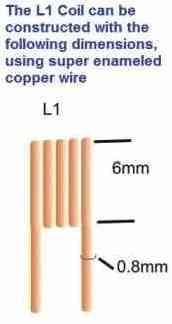
- Make coil L1 and take 0.5 mm wire and turn it 6 times around 3 mm stick or pen.
- Connect this coil inductor strong and tight into the circuit.
- Use 7 cm long 1 mm thick copper wire with plastic cover for antenna.
- Connect antenna directly to oscillator circuit.
- Choose power like battery of 5t o12V adapter or 5V USB any one is OK.
- Connect power to circuit.
- Turn trimmer P1 to middle position not to full left or right.
- Switch on FM radio and find empty frequency between 87.5 and 108 MHz with no sound.
- Power on transmitter and change coil L1 with twist or stretch a bit to come close to that frequency.
- Use trimmer P1 now for fine tuning.
- When radio sound stop it means we can catch the signal.
- Now connect the music player like record player, CD/MP3, cassette or laptop to the transmitter input.
Testing:
- Check all wires and parts and be sure connection is correct and safe.
- Turn ON the transmitter and also the audio player.
- Tune the FM radio to the frequency which is been set and one can hear its audio playing.
Things to Remember:
- If power voltage changes the varicap voltage also changes and this can move the frequency.
- Antenna is connected direct to oscillator because of that if we touch antenna or move it frequency can also change.
Another 100 meter Transmitter Circuit using BC547 Transistor:

Parts List:
| Component | Description | Quantity |
|---|---|---|
| Resistors | All resistors are 1/4 W CFR | |
| 3.3k | 1 | |
| 100k | 1 | |
| 1k | 1 | |
| Capacitors | ||
| Ceramic 10pF | 1 | |
| Ceramic 102pF | 1 | |
| Ceramic 27pF | 2 | |
| Electrolytic 1µF 16V | 1 | |
| Semiconductors | ||
| Transistor BC547 | 1 | |
| Battery 3V | 1 | |
| Electret Mic | 1 | |
| Coil as shown in image | 1 |
We have introduce new small wireless FM transmitter which is like tiny RF transmitter and is made using only one transistor.
This circuit work same like Colpitts oscillator and has a tank circuit which make the needed radio waves.
Parts like coil, C1, C2 and C3 are their place and value decides what frequency come out.
If we change coil turns or change coil shape or size it can affect how far the signal go and how radio can catch it.
A small antenna which is just 3 inch wire is put at right spot to help signal connect better and clean with no distortion.
These small changes make transmitter work better and now it is more strong, more stable and useful.
Formulas:
Use these formulas for FM Transmitter Circuit (100 meters range):
First collect all parts like transistor, inductor (coil) and capacitors C1, C2, C3.
Put coil (inductor) in right place and change values of C1, C2 and C3 to build tank circuit.
To find frequency use this formula:
f = 1 / (2 × π × √(L × C))
where:
- f is frequency
- π is 3.14159 math number
- L is inductance coil
- C is capacitance in capacitor
To get better signal on FM radio change coil and make it wider or change spacing between turns.
We can calculate new frequency with this formula:
fadjusted = finitial × (dadjusted / dinitial) × (Dadjusted / Dinitial)
where:
- fadjusted is new frequency
- finitial is starting frequency
- dadjusted is new space between coil turns
- dinitial is original space between turns
- Dadjusted is new coil diameter
- Dinitial is original coil diameter
Use 3 inch wire with covered copper as antenna.
Put it in right place and it will help the signal to go far and clear.
When we do these small changes transmitter will work much better.
To get best result and clean signal follow these steps carefully.
How to Build:
Steps to Build Wireless FM Transmitter Circuit:
- Place transistor T1 on PCB (printed board).
- Solder emitter, base and collector legs of transistor to correct places on board.
- Before putting inductor L1 be sure it is made correct and connected properly.
- Connect capacitor C1 between collector and base of transistor.
- Connect capacitor C2 between base and ground.
- Connect capacitor C3 between collector and emitter.
- Now L1, C1, C2 and C3 together make tank circuit and this circuit makes the radio waves oscillations.
- To change frequency change values or position of capacitors and coil.
- To make transmitter faster and better adjust coils diameter and distance between turns.
- Use frequency formulas to calculate new frequency after coil changes.
- At correct place in circuit connect a 3 inch long wire which is the antenna.
- It helps send signal better and more clear.
- Give power to circuit like 3V battery or other good power source.
Testing:
- Turn ON the FM transmitter.
- Use FM radio to find the frequency where our signal is coming.
- Be sure sound is clear with no noise or distortion.
- Try small changes and tuning to get best signal and correct working frequency.
Conclusion:
It is important to remember rules for using FM Transmitter Circuit (100 meters range).
We must follow steps of FM Transmitter Circuit carefully and also respect local law for FM broadcasting.
Every country have different rules so before using check if it is legal in anyone place.
Twell-wander can be probliant with snimple transmint circuit. Solic construnct-buildre is need for ‘lock-a-lock’ to frequently. Also with temprementure, drinft can occur, boxidge in round-stylery can pook extra-resumptivenents.
Hi,
Yes correct, simple transmitter circuits can drift, use strong construction, short wiring and stable components to reduce this problem.
thanks.
I WANT TO TRY FOR ENTERMENT
sure, please give it a try.