The “Hee Haw” Siren Circuit is a fun sound project that makes a high and low noise like “Hee Haw” instead of one long sound.
Also, simple electronic components such as resistors, capacitors, transistors and sometimes ICs make up the circuit.
The pitch of the sound goes up and down again and again and we can find it in toys, alarms or fun DIY projects.
Furthermore, it sounds like a cartoon siren and gets its name because it sounds like someone saying “Hee Haw” like a funny donkey noise.
Circuit Working:
Parts List:
| Components | Values | Quantity |
|---|---|---|
| Resistors (All resistors are 1/4 watt unless specified) | 220Ω | 2 |
| 5.6k | 2 | |
| 100k | 2 | |
| 3.9k | 2 | |
| Capacitors | Ceramic 100nF | 2 |
| Electrolytic 100µF 25V | 3 | |
| Semiconductors | Transistor BC547 | 4 |
| Transistor BC557 | 1 | |
| LEDs any 5mm, 20mA | 2 | |
| Speaker 8Ω | 1 |
This circuit uses two astable multivibrators also called oscillators that create signals without needing outside input.
One oscillator runs slower and controls the faster one and this changes in speed that creates the “Hee Haw” sound.
How it works:
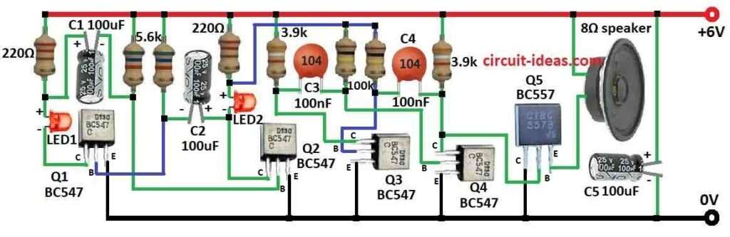
The first part uses two BC547 transistors Q1 and Q2, two 100uF capacitors C1 and C2, three resistors 3.9k, 5.6k and 220Ω, and an LED.
Capacitor C1 sets the speed of this low-frequency oscillator and when Q1 turns ON it charges C1 through the 5.6k resistor.
Also, as C1 charges the Q1 turns OFF and Q2 turns ON and C1 then discharges through the 220Ω resistor and LED, by making the LED blink.
Therefore, this cycle keeps repeating, creating a slow flashing signal.
Then the second part uses two more BC547 transistors Q3 and Q4, two 100nF capacitors C3 and C4, and two 220Ω resistors.
This part runs faster and creates the siren sound; the slow oscillator controls Q3 which changes the sound frequency.
Moreover, the circuit connects a speaker to Q4 through an 8 Ω resistor and the changing voltage at Q4 produces the ‘Hee Haw’ sound
We can change how the siren sounds by using different capacitor or resistor values.
Even though this circuit is simple, always handle electronics carefully and use a proper power supply, avoid electric shock hazards, and seek help from an experienced person if we are unsure about any part of the project.
Formulas:
These formulas calculate the frequency and timing of an astable multivibrator.
Main Formulas:
1. Frequency (f):
f =1 / T
where,
- T is the total time of one full cycle.
2. Time Periods T1 and T2:
T1 = 0.693 × (R1 + R2) × C
Time capacitor charges through R1 and R2
T2 = 0.693 × R2 × C
Time capacitor discharges through R2
3. Total Time (T):
T=T1+T2
This is the total period of the oscillation.
4. Duty Cycle (D):
D = T1 / T
This shows the ratio of ON time T1 to the full period.
We can use these formulas to build the multivibrator with basic components such as transistors, resistors and capacitors
But keep in mind the real circuit values and design can affect the exact frequency and duty cycle and these formulas give us a good starting point.
How to Build:
To build a “Hee Haw” Siren Circuit follow the below mentioned connections steps:
Q1 Transistor Connection:
- First, connect the collector to the positive side using LED1 and a 220Ω resistor, connect the base to the end side of the 5.6k resistor and connect the emitter to ground.
Q2 Transistor Connection:
- Then connect the collector to the positive side using LED2 and a 220Ω resistor, connect the base to the starting side of the 5.6k resistor and then connect the emitter to ground.
Q3 Transistor Connection:
- After that, connect the collector to a 3.9k resistor, connect the base to the end side of a 100k resistor and then connect the emitter to ground.
Q4 Transistor Connection:
- Now connect the collector to the other side of the 3.9k resistor, connect the base to the starting side of the 100k resistor and then connect the emitter to ground.
Q5 Transistor Connection:
- Next, connect the collector to ground, connect the base between Q4s collector and the 3.9k resistor and then connect the emitter to one end of the speaker.
Safety Tip:
- This circuit uses low voltage but still we need be careful.
- Check all connections before turning it on and use a power supply with the right voltage.
Conclusion:
Overall, the “Hee Haw” Siren Circuit is a fun project that makes a two-tone sound like a funny siren, as it works using oscillators that control the sound.
Also, it is not for real emergencies, but it is a great way to learn electronics and have fun; but always stay safe when working with electronic circuits.
Leave a Reply